Monitoring and Troubleshooting
7-17
8700-A2-GB20-00
April 2000
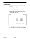
Viewing LED Status
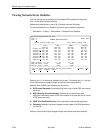
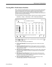
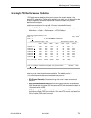
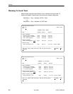
The unit LEDs can be viewed on the Display LEDs Status screen, available
locally and remotely.
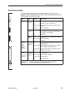
The LEDs are organized into three groups:
H System LEDs display the status of the unit
H DSX-1 or G.703 LEDs provide the status of the DTE interface
H DSL Loop LEDs display the activity on the DSL network
To view the Display LEDs status screen, follow this menu selection sequence:
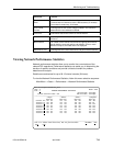
Main Menu →Status → Display LEDs
main/status/leds
Slot: 18 Model: 87xx
DISPLAY LEDs
SYSTEM DSX-1|G.703 Port DSL LOOP
––––––––––––––––––––––––––––––––––––––––––––––––––––––––––––––––––––––––––––––––
Alarm Off P1:Link Up P1:Link Up
Test Off P2:Link Up P2:Link Up
P3:Link Up P3:Disabledp
P4:Link Up P4:Link Up
P5:Link Up P5:Link Up
P6:Link Up P6:Link Up
P7:Link Up P7:Link Up
P8:Link Up P8:Link Up
––––––––––––––––––––––––––––––––––––––––––––––––––––––––––––––––––––––––––––––––
ESC for previous menu M
ainMenu Exit
The LED status display screen is updated every 5 seconds.
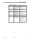
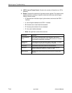
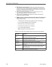
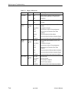
Table 7-5 shows the meaning of the possible values for each LED represented.


