


6 March 2005 BSX8-A2-GZ40-10
MIM-4000F
The MIM-4000F is a four-port fiber gigabit Ethernet interface connecting directly to
the gigabit Ethernet switch in the BSX8000-5 uplink module.
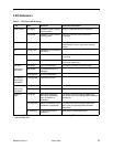
MIM-2E1
Plug your E1 cable into one of the RJ45 E1 ports on the MIM-2E1 faceplate. The
MIM-2E1 connects to an E1 network extender provider unit (ENE2000-P or, for
loop bonding, ENE2020-P) via a standard E1 line.
Verify the connection: the Lnk (link) LED on the MIM-2E1 faceplate flashes green
to indicate a network connection has been established.
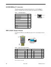
MIM-2T1
Plug your T1 cable into one of the RJ45 T1 ports on the MIM-2T1 faceplate. The
MIM-2T1 connects to a T1 network extender provider unit (TIM1500-12,
TIM1500-24, TNE1500, or TNE1520) via a standard T1 line.
Verify the connection: the Lnk (link) LED on the MIM-2T1 faceplate flashes green
to indicate a network connection has been established.
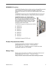
BLC Management
The BSX8000-5 uplink module provides BLC management capability via the
Command Line Interface (CLI), Simple Network Management Protocol (SNMP),
and the web-based Network Management System (NMS).
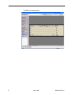
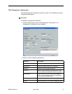
Web Interface (NMS)
The following are required for use of the NMS:
Web Browser – Required for running NMS. Compatible web browsers
include, but are not limited to, Microsoft Internet Explorer (version 6.0 or
higher) and Netscape Navigator (version 6.0 or higher). NMS is optimized for
use with Internet Explorer.
Use your browser's default settings when running NMS. JavaScript must be
enabled.
Screen Resolution – 1024 x 768 pixels is the minimum resolution required for
all NMS views to fit within the dimensions of most monitors and laptops. Lower
screen resolutions (such as 800 x 600 pixels) may cause NMS screens to
exceed the width or height of the screen. To verify screen resolution on a
Windows system:
— Right click on your desktop
— Select Properties
— Click the Settings tab
— Adjust the Screen Resolution as needed