


MIM2-A2-GZ42-00 June 2005 3
Product Documentation Online
Complete documentation for Paradyne products is available at
www.paradyne.com. Select Support → Technical Manuals.
To order a paper copy of a Paradyne document, or to speak with a sales representative,
please call 1-727-530-2000.
Unpacking and Inspecting the Equipment
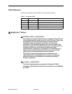
HANDLING PRECAUTIONS FOR
STATIC-SENSITIVE DEVICES
This product is designed to protect sensitive components from damage
due to electrostatic discharge (ESD) during normal operation. When
performing installation procedures, however, take proper static control
precautions to prevent damage to equipment. If you are not sure of the
proper static control precautions, contact your nearest sales or service
representative.
If there is any visible damage, do not attempt to install the MIM-2000F; contact
your sales representative.
Installing the MIM-2000F
The MIM-2000F Micro Interface Module provides additional uplink ports for the
BSX8000-5 Broadband Services Switch or 4929 DSLAM.
All MIMs are hot-swappable, although removal of a MIM disengages the upstream
network connection for the DSLAM.
To install the MIM-2000F:
Procedure
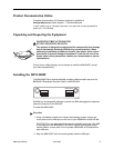
1. Using a flat-blade screwdriver to loosen the fastening screws, remove the
cover plate from the MIM port on the front of your BSX8000 or 4929 DSLAM.
CAUTION: The cover plate should be stored for possible future use. If the MIM
is removed from your BSX8000 or DSLAM, it must be replaced with either
another MIM or a cover plate. Do not operate a BSX8000 or DSLAM with an
open MIM port.
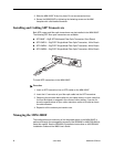
2. Align the MIM-2000F with the module guides inside the MIM port.
!
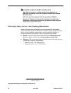
Lnk 1 Act Lnk 2 Act
MIM-2000F
05-17669