


4.0 INSTALLATION
Once the Model 1004 is properly configured, it is ready to connect
to your system. This section tells you how to properly connect the
Model 1004 to the twisted pair and RS-232 interfaces, and how to
operate the Model 1004.
4.1 TWISTED PAIR CONNECTION
The Model 1004 supports data-only communication between two
RS-232 devices at distances to 9.4 miles and data rates to 115.2 Kbps.
There are two essential requirements for installing the Model 1004:
1. These units work in
pairs.
Therefore, you must have one Model
1004 at each end of a two twisted pair interface. In multipoint
environments, there must be one Model 1004 at the RS-232 host
and one at each RS-232 terminal.
2. To function properly, the Model 1004 needs two twisted pairs of
metallic wire. These pairs must be
unconditioned
dry metallic
wire, between 19 and 26 AWG (the higher number gauges may
limit distance). Standard dial-up telephone circuits, or leased cir-
cuits that run through signal equalization equipment, are
not
acceptable
.
For your convenience, the Model 1004 is available with several
different twisted pair interfaces: RJ-11 jack, RJ-45 jack, terminal
blocks with strain relief and dual modular jacks (for multipoint daisy-
chaining).
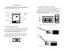
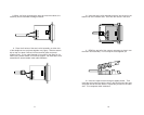
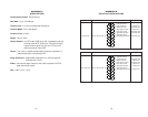
4.1.1 TWISTED PAIR CONNECTION USING TERMINAL BLOCKS
If your application requires you to connect one or two pairs of bare
wires to the Model 1004, you will need to open the case to access the
terminal blocks. The following instructions will tell you how to open the
case, connect the bare wires to the terminal blocks and fasten the
strain relief collar in place so the wires won't pull loose.
1. You should already have the case open for the configuration
procedure. If not, see Section 3.2.
2. Strip the outer insulation from the twisted pair(s) about one
inch from the end.
7
3. Strip the insulation on each of the twisted pair wires about .25”.
4. In a two pair circuit, connect
one pair
of wires to XMT+ and
XMT- (transmit positive and negative) on the terminal block, making
careful note of which color is positive and which color is negative.
5. Connect the
other pair
of wires to RCV+ and RCV- (receive
positive and negative) on the terminal block, again making careful note
of which color is positive and which color is negative.
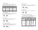
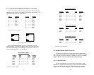
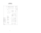
Ultimately, you will want to construct a two pair crossover cable that
makes a connection with the two Model 1004s as shown below.
6. In a single pair circuit, use
only the transmit (XMT) pair
as
shown below:
7. If there is a shield around the telephone cable, it may be con-
nected to “G” on the terminal block. To avoid ground loops, we recom-
mend connecting the shield at the computer end only. A ground wire is
not necessary
for proper operation of the Model 1004.
8
XMT+--------------------------------------------------RCV+
XMT- --------------------------------------------------RCV-
G ---------------------- G
RCV+--------------------------------------------------XMT+
RCV- --------------------------------------------------XMT-
To Shield (Optional)
}
One Pair
}
One Pair
XMT+--------------------------------------------------XMT+
XMT- --------------------------------------------------XMT-