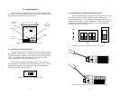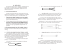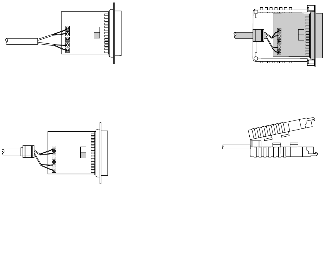
8. When you finish connecting the wires to the terminal block, the
assembly should resemble the diagram below:
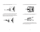
9. Place the 2 halves of the strain relief assembly on either side
of the telephone wire and press together very lightly. Slide the assem-
bly so that it is about 2 inches from the terminal posts and press
together firmly. If your cable diameter is too small or too large for our
strain relief, please contact our technical support. We have strain relief
assemblies to accommodate most cable diameters.
+RCV- G -XMT+
+RCV- G -XMT+
9
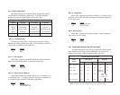
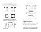
10. Insert the strain relief assembly and wire into the slot in the
bottom half of the modem case. Set it into the recess in the case.
11. BEND the top half of the case as necessary to place it over
the strain relief assembly. Do not snap the case together yet.
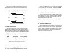
12. Insert one captive screw through a saddle washer. Then
insert the entire piece through the hole in the DB-25 end of the case.
Snap that side of the case closed. Repeat the process for the other
side. This completes cable installation.
10


