APPENDIX B
PATTON MODEL 1005 CABLE RECOMMENDATIONS
The Patton Model 1005 operates at frequencies of 20kHz or less
and has been performance tested by Patton technicians using twisted-
pair cable with the following characteristics:
Wire Gauge Capacitance Resistance
19 AWG/.9mm 83nf/mi or 15.72 pf/ft. .0163 Ohms/ft.
22 AWG/.6mm 83nf/mi or 15.72 pf/ft. .0326 Ohms/ft.
24 AWG/.5mm 83nf/mi or 15.72 pf/ft. .05165 Ohms/ft.
To gain optimum performance from the Model 1005, please keep
the following guidelines in mind:
• Alwaysuse twisted pairwire—this is not an option.
• Use twisted pair wire with a capacitance of 20pf/ft or less.
• Avoid twisted pair wire thinner than 26 AWG (i.e. avoid higher
AWGnumbers than 26)
• Use of twisted pair with a resistance greater than the above
specifications may cause a reduction in maximum distance
obtainable. Functionality should not be affected.
• Environmental factors too numerous to mention can affect the
maximum distances obtainable at a particular site. Use “maximum
distance” figures as a general guideline only.
APPENDIX A
PATTON MODEL 1005 SPECIFICATIONS
Transmission Format: Asynchronous
Data Rate: 0 to 19,200 bps (no strapping)
Control Signal: DCE Mode:CTS (Pin 5) turns ON immediately after
the terminal raises RTS (Pin 4); DSR (Pin 6) turns on when is
powered-up (connected); DCD (Pin 8) turns ON after detecting the
receive signal from the line; DTE Mode:RTS (Pin 4) turns “ON”
immediately after the modem raises CTS (Pin 5); DTR (Pin 20)
turns "ON" after recognizing the receive signal from the line; Pins
11, 19 and 20 are hardwired together on the DB-25 side of the
DCE/DTE switch
Transmit Line: 4-wire, unconditioned line
Transmit Mode: Full duplex, 4-wire
Transmit Level: 0 dBm
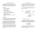
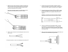
Connection: Either a male or female DB-25
Line Connection: RJ-11 or RJ-45 jack or 5 screw terminal posts
(4 wires and 1 ground) and a strain relief insert
Power Supply: No additional power required, uses ultra low power
from EIA data and control signals; additional power can be added
at pin 9 for +V DC when DB-25 is below the RS-232 standard
requirements
Surge Protection: Compliant with IEC 801.5 level 2, 1kV (Model
1005S Only)
Size:2.66” x 2.10” x 0.73” (6.76 x 5.33 x 1.85 cm)
11 12
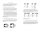
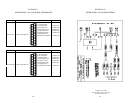
24 AWG
(0.5 mm)
26 AWG
(0.4 mm)
19 AWG
( 0.9 mm)
19,200 6.2(10.0) 3.7(6.0) 1.2(1.9)
9,600 7.5(12.1) 4.9(7.9) 2.5(4.0)
4,800 8.7(14.0) 5.6(9.0) 3.7(6.0)
2,400 11.8(19.0) 8.0(12.9)4.9(7.9)
1,200 17.0(27.4)11.8(19.0)8.0(12.9)
Data Rate
(bps)
Model 1005 Distance Table in Miles (km)
Wire Gauge