


APPENDIX A
PATTON MODEL 1006 SPECIFICATIONS
Transmission Format: Asynchronous
Data Rate: 0 to 19,200 bps (no strapping)
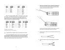
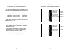
Distance: See table below
Surge Protection: Compliant with IEC 801.5 level 2, 1kV (Model
1006S Only)
Control Signal: CTS (Pin 8) turns ON immediately after the terminal
raises RTS (Pin 7); DSR (Pin 6) turns on when it is powered-up
(connected); DCD (Pin 1) turns ON after detecting the receive
signal from the line
Transmit Line: 4-wire, unconditioned line
Transmit Mode: Full duplex, 4-wire
Transmit Level: 0 dBm
RS-232 Connection: DB-9
Line Connection: RJ-11 or RJ-45 jack or 5 screw terminal posts
(4 wires and 1 ground) and a strain relief insert
Power Supply: No external power required, uses ultra low power
from EIA data and control signals
Size: 2.5” x 1.2” x 0.75” (6.4 x 3.0 x 1.9 cm)
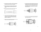
10. TIP the top half of the case as necessary to place it over the
strain relief assembly. Do not snap the case together yet.
11. Insert one captive screw through a saddle washer and then
insert the entire piece through the hole in the DB-9 end of the
case. Snap that side of the case closed. Repeat the process
for the other side. This completes cable installation.
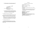
3.2 CONNECTION TO THE RS-232 INTERFACE
Once you have connected the twisted pair wires correctly, simply
plug the Model 1006 directly into the DB-9 port of the RS-232 device.
Remember to insert and tighten the two captive connector screws.
NOTE:If you must use a cable to connect the Model 1006 to the
RS-232, make sure it is a straight throughcable of the shortest
possible length—we recommend 6 feet or less. The Model 1006
requires a cable that incorporates pins 1, 2, 3, 4, 5, 6, 7 and 8.
3.3 OPERATING THE MODEL 1006
Once the Model 1006 is properly installed, it should operate
transparently—as if it were a standard cable connection. Operating
power is derived from the RS-232 data and control signals; there is no
“ON/OFF” switch.
9 10