


APPENDIX B
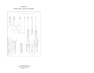
PATTON MODEL 1006 CABLE RECOMMENDATIONS
The Patton Model 1005 operates at frequencies of 20kHz or less
and has been performance tested by Patton technicians using twisted-
pair cable with the following characteristics:
Wire Gauge Capacitance Resistance
19 AWG/.9mm 83nf/mi or 15.72 pf/ft. .0163 Ohms/ft.
22 AWG/.6mm 83nf/mi or 15.72 pf/ft. .0326 Ohms/ft.
24 AWG/.5mm 83nf/mi or 15.72 pf/ft. .05165 Ohms/ft.
To gain optimum performance from the Model 1006, please keep
the following guidelines in mind:
• Alwaysuse twisted pairwire—this is not an option.
• Use twisted pair wire with a capacitance of 20pf/ft or less.
• Avoid twisted pair wire thinner than 26 AWG (i.e. avoid higher
AWGnumbers than 26)
• Use of twisted pair with a resistance greater than the above
specifications may cause a reduction in maximum distance
obtainable. Functionality should not be affected.
• Environmental factors too numerous to mention can affect the
maximum distances obtainable at a particular site. Use “maximum
distance” figures as a general guideline only.
APPENDIX C
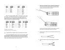
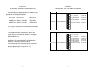
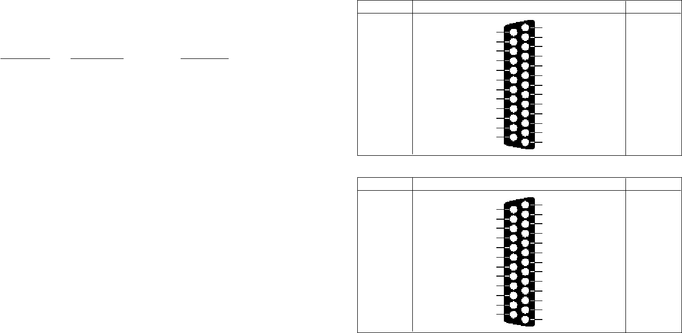
PATTON MODEL 1006 PIN/SIGNAL ASSIGNMENTS
1- (FG) Frame Ground
2- (TD) Transmit Data To Model 1006
3- (RD) Receive Data From Model 1006
4- (RTS) Request to Send To Model 1006
5- (CTS) Clear to Send From Model 1006
6- (DSR) Data Set Ready From Model 1006
7- (SG) Signal Ground
8- (DCD) Data Carrier Detect From Model 1006
To Model 1006 Data Term. Ready (DTR) - 20
DIRECTION STANDARD “DCE” SETTING DIRECTION
1- (FG) Frame Ground
2- (TD) Transmit Data From Model 1006
3- (RD) Receive Data To Model 1006
4- (RTS) Request to Send From Model 1006
5- (CTS) Clear to Send To Model 1006
6- (DSR) Data Set Ready To Model 1006
7- (SG) Signal Ground
8- (DCD) Data Carrier Detect To Model 1006
From Model 1006Data Term. Ready (DTR) - 20
DIRECTION STANDARD “DTE” SETTING DIRECTION
11 12