


4.0 INSTALLATION
Once you have properly configured the DTE/DCE switch, you are
ready to connect the Model 1010A to your system. This section tells
you how to properly connect the Model 1010A to the twisted pair and
RS-232 interfaces, and how to operate the Model 1010A.
4.1 CONNECTION TO THE TWISTED PAIR INTERFACE
The Model 1010A supports data-only communication between two
RS-232 devices at distances to 8.5 miles and data rates to 115.2 Kbps.
There are two essential requirements for installing the Model 1010A:
1) These units work in
pairs
. Therefore, you must have one Model
1010A at each end of a two twisted pair interface.
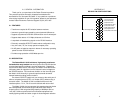
2) To function properly, the Model 1010A needs two twisted pairs of
metallic wire. These pairs must be
unconditioned
, dry metallic wire,
between 19 and 26 AWG (the higher number gauges may limit distance
somewhat). Standard dial-up telephone circuits, or leased circuits that
run through signal equalization equipment, are
not acceptable
.
For your convenience, the Model 1010A is available with three
different twisted pair interfaces: RJ-11 jack, RJ-45 jack and terminal
blocks with strain relief.
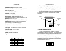
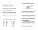
4.1.1 TWISTED PAIR CONNECTION USING RJ-11 OR RJ-45
The RJ-11 and RJ-45 connectors on the Model 1010A's twisted pair
interface are pre-wired for a standard TELCO wiring environment. The
signal/pin relationships are shown below:
RJ-1
1 SIGNAL RJ-45 SIGNAL
1...................GND* 1 .................N/C
2...................RCV- 2 .................GND*
3...................XMT+ 3 .................RCV-
4...................XMT- 4 .................XMT+
5...................RCV+ 5 .................XMT-
6...................GND 6 .................RCV+
7 .................GND
8 .................N/C
4
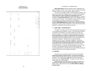
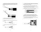
10. BEND the top half of the case as necessary to place it over the
strain relief assembly. Do not snap the case together yet.
11. Insert one captive screw through a saddle washer, then insert
the captive screw with the washer on it through the hole in the DB-25
end of the case. Snap that side of the case closed. Repeat the
process for the other side. This completes cable installation.
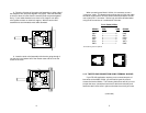
4.2 CONNECTION TO THE RS-232 INTERFACE
Once you have configured the Model 1010A for DTE or DCE and
connected the twisted pair wires correctly, all that remains is to plug the
1010A directly into the DB-25 port of the RS-232 device. After doing
so, remember to insert and tighten the two captive connector screws.
(Note: If you must use a cable to connect the Model 1010A to the
RS-232 device, make sure it is a
straight through
cable of the shortest
possible length—we recommend 6 feet or less).
4.3 OPERATING THE MODEL 1010A
Once the Model 1010A is properly installed, it should operate
transparently—as if it were a standard cable connection. Operating
power is derived from the RS-232 data and control signals; there is no
"ON/OFF" switch. All data signals from the RS-232 interface are
passed straight through. All control signals from the RS-232 interface
are looped back.
(Note: If your system requires
hardware
flow control, you will need the
Patton Model 1012 or Model 1060 Short Range Modem. Call Patton
Customer Service at 301-975-1007 for more information).
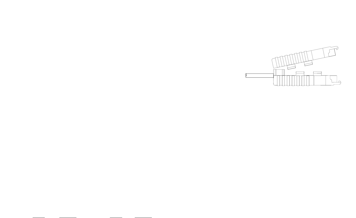
+RCV- G -XMT+
+RCV- G -XMT+
+RCV- G -XMT+
9