


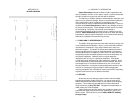
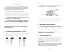

When connecting two Model 1010As, it is necessary to use a
"cross over" cable. The diagram below shows how a cross over cable
should be constructed for an environment where both Model 1010As
use a 6-wire RJ-11 connector. Similar logic should be followed when
using RJ-45 connectors or a combination of the two.
RJ-1
1 Cable (4-Wire)
SIGNAL PIN# PIN# SIGNAL
GND
†
1-----------------------6 GND
†
RCV- 2-----------------------4 XMT-
XMT+ 3-----------------------5 RCV+
XMT- 4-----------------------2 RCV-
RCV+ 5-----------------------3 XMT+
GND
†
6-----------------------1 GND
†
†
Connection to ground is optional
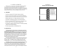
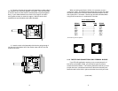
4.1.2 TWISTED PAIR CONNECTION USING TERMINAL BLOCKS
If your RS-422 application requires you to connect two pairs of
bare wires to the Model 1010A, you will need to open the case to
access the terminal blocks. The following instructions will tell you how
to open the case, connect the bare wires to the terminal blocks, and
fasten the strain relief collar in place so that the wires won't pull loose.
(continued)
5
1
2
3
4
5
6
1
2
3
4
5
6
7
8
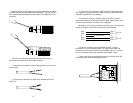
8. Place the 2 halves of the strain relief assembly on either side of
the telephone wire and press together very lightly. Slide the assembly
so that it is about 2 inches from the terminal posts and press together
firmly. If your cable diameter is too small or too large for our strain
relief, please contact our technical support. We have strain relief
assemblies to accommodate most cable diameters.
9. Insert the strain relief assembly with the wire going through it
into the slot in the bottom half of the modem case and set it into the
recess in the case.
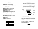
DCE DTE
+RCV- G -XMT+
+RCV- G -XMT+
+RCV- G -XMT+
DCE DTE
+RCV- G -XMT+
+RCV- G -XMT+
+RCV- G -XMT+
8