


3.0 CONFIGURATION
The Model 1015 is designed to be easy to use. There are no
internal jumpers or configuration switches to set, so there is no need to
open the case to configure the unit (you may need to open the case for
wire connection—refer to section 4.0). However, in some models, you
may have to set the external DCE/DTE switch.
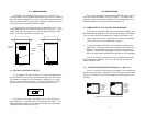
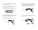
The figure below shows both versions of the Model 1015. If your
model looks like Figure 1, follow the instructions in Section 3.1. If your
Model 1015 looks like Figure 2, your unit will always operate in DCE
mode. Follow the instructions in Section 4.0.
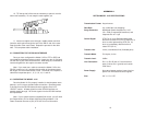
3.1 SETTING THE DCE/DTE SWITCH
If your Model 1015 looks like Figure 1, it comes equipped with an
external DCE/DTE switch and requires special attention. If the device
connected to the Model 1015 is a modem or multiplexer (or is wired
like one), move the switch to “DTE”. This causes the Model 1015 to
behave like Data Terminal Equipment and transmit data on pin 1.
If the device connected to the Model 1015 is a PC, terminal or
host computer (or is wired like one), move the switch to “DCE”. This
setting causes the Model 1015 to behave like Data Communications
Equipment and transmit data on pin 9.
4.0 INSTALLATION
Once you have properly configured the DCE/DTE switch, you are
ready to connect the Model 1015 to your system. This section tells
you how to properly connect the Model 1015 to the twisted pair and
RS-232 interfaces, and how to operate the Model 1015.
4.1 CONNECTION TO THE TWISTED PAIR INTERFACE
The Model 1015 supports data-only communication between two
RS-232 devices at distances to 17 miles and data rates to 19.2 Kbps.
There are two essential requirements for installing the Model 1015:
1. These units work in pairs. Therefore, you must have one Model
1015 at each end of a two twisted pair interface.
2. To function properly, the Model 1015 needs two twisted pairs of
metallic wire. The pairs must be unconditioned, dry metallic wire,
between 19 and 26 AWG (the higher number gauges may limit
distance). Standard dial-up telephone circuits, or leased circuits
that run through signal equalization equipment are not acceptable.
For your convenience, the Model 1015 is available with three dif-
ferent twisted pair interfaces: RJ-11 jack, RJ-45 jack and terminal
blocks with strain relief.
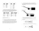
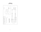
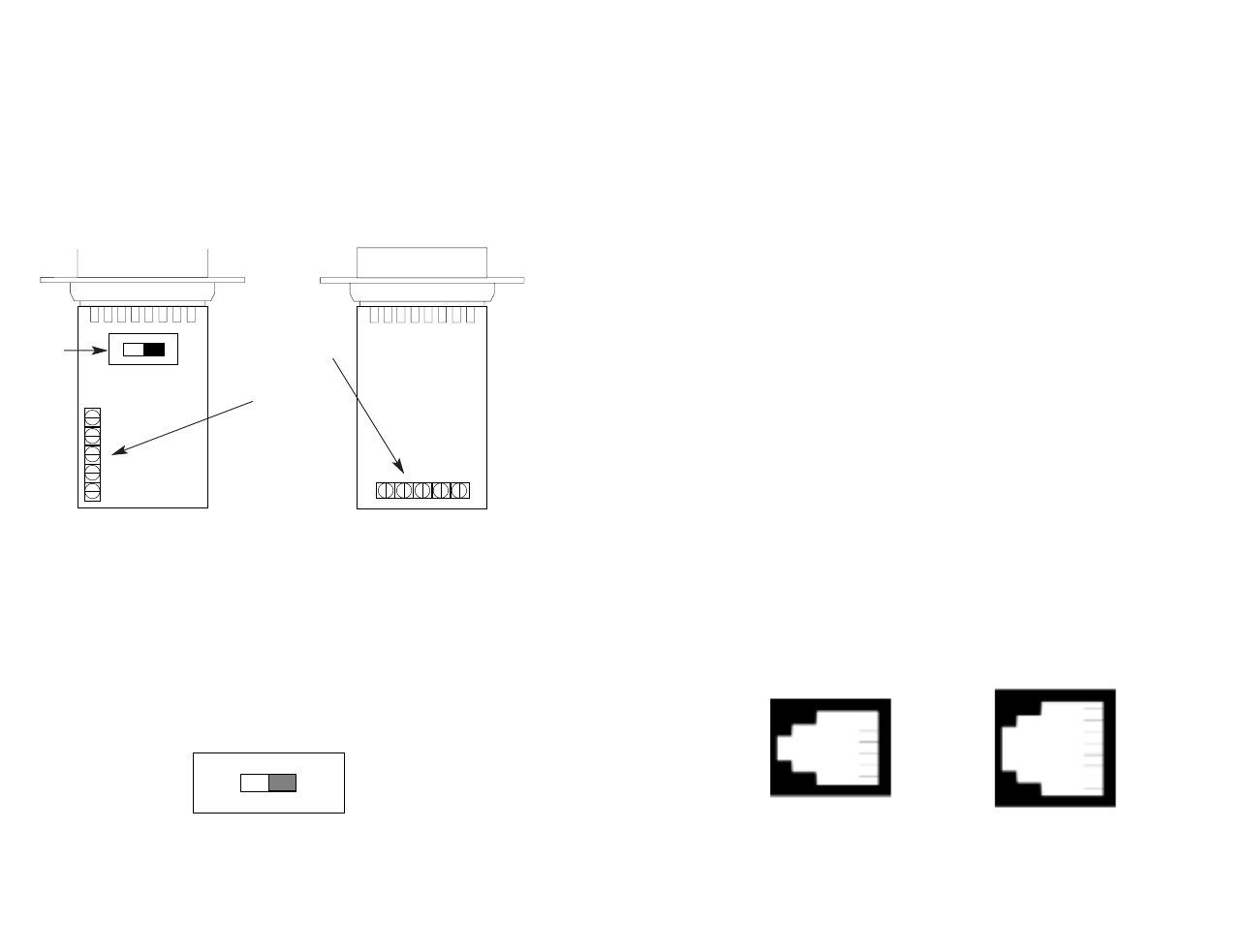
4.1.1 TWISTED PAIR CONNECTION USING RJ-11 OR RJ-45
The RJ-11 and RJ-45 connectors on the Model 1015’s twisted pair
interface are pre-wired for a standard TELCO wiring environment (see
Figure 3). The table on the following page shows the signal/pin rela-
tionships:
3 4
DCE/DTE
Switch
Terminal
Block
Terminal
Block
DCE DTE
1 - Blue
2 - Orange
3 - Black
4 - Red
5 - Green
6 - Yellow
7 - Brown
8 - Slate
1 - Blue
2 - Yellow
3 - Green
4 - Red
5 - Black
6 - White
Figure 3. AT&T standard modular color codes
Figure 2Figure 1