


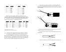
4. Connect
one pair
of wires to XMT+ and XMT- (transmit positive
and negative) on the terminal block, making careful note of which color
is positive, and which color is negative.
5. Connect the
other pair
of wires to RCV+ and RCV- (receive
positive and negative) on the terminal block, again making careful note
of which color is positive and which color is negative.
Ultimately, you will want to construct a two pair crossover cable
that makes a connection with the RS-232 device as shown below:
6. If there is a shield around the telephone cable, it may be con-
nected to “G” on the terminal block. To avoid ground loops, we recom-
mend connecting the shield at the computer end only. A ground wire is
not necessary
for proper operation of the Model 1015.
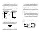
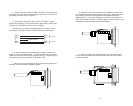
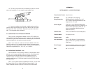
7. When you finish connecting the wires to the terminal block, the
assembly should resemble the diagram below:
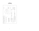
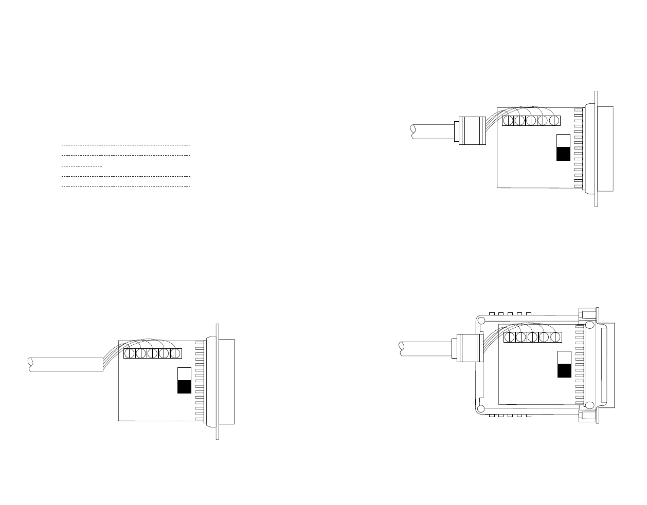
8. Place the 2 halves of the strain relief assembly on either side
of the telephone wire and press together very lightly. Slide the assem-
bly so that it is about 2 inches from the terminal posts and press
together firmly. If your cable diameter is too small or too large for our
strain relief, please contact our technical support. We have strain relief
assemblies to accommodate most cable diameters.
9. Insert the strain relief assembly with the wire going through it
into the slot in the bottom half of the modem case and set it into the
recess in the case.
87
+XMT- G -RCV+
+XMT- G -RCV+
XMT + RCV+
XMT - RCV -
GG
RCV - XMT -
RCV + XMT +
To Shield (Optional)
}
One Pair
}
One Pair