


12
4.0 INSTALLATION
Once the Model 1052 has been configured, it is ready to connect to the
twisted pair interface, to the serial port, and to the power source. This
section tells you how to make these connections.
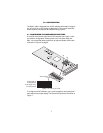
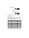
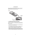
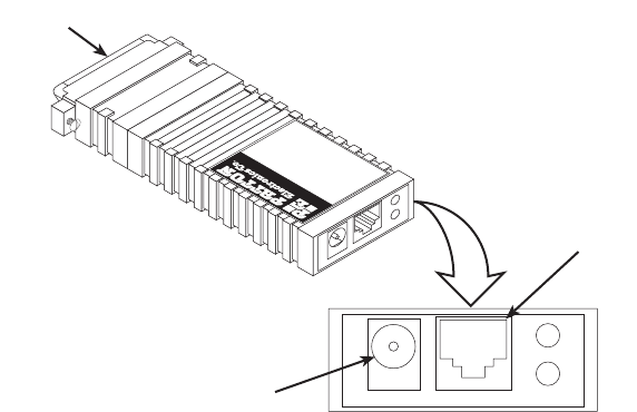
Figure 3.
Model 1052 Rear Panel
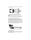
4.1 CONNECTING THE TWISTED PAIR INTERFACE
The Model 1052 supports communication between two DTE devices at
distances to 5 miles (8 km) over 24 AWG (0.5mm) twisted pair wire. Two
things are essential:
• These units work in pairs. Both units at the end of the twisted pair DSL
span must be set for the same DTE rate.
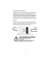
• To function properly, the Model 1052 needs one twisted pair of metallic
wire. This twisted pair must be unconditioned, dry, metallic wire,
between 19 (0.9mm) and 26 AWG (0.4mm) (the higher number
gauges will limit distance). Standard dial-up telephone circuits, or
leased circuits that run through signal equalization equipment, or stan-
dard, flat modular telephone type cable, are not acceptable. The RJ-45
connector on the Model 1052’s twisted pair interface is polarity insensi-
RS-232
port
RJ-45 DSL
interface
Power jack
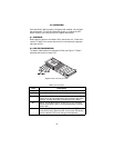
Gaithersburg, Maryland
Model
1052/A
iDSL Model With
RS-232 Interface
TXD
RXD
DSL LINK
NS
ER