


8
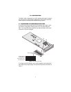
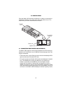
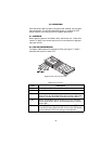
Figure 2.
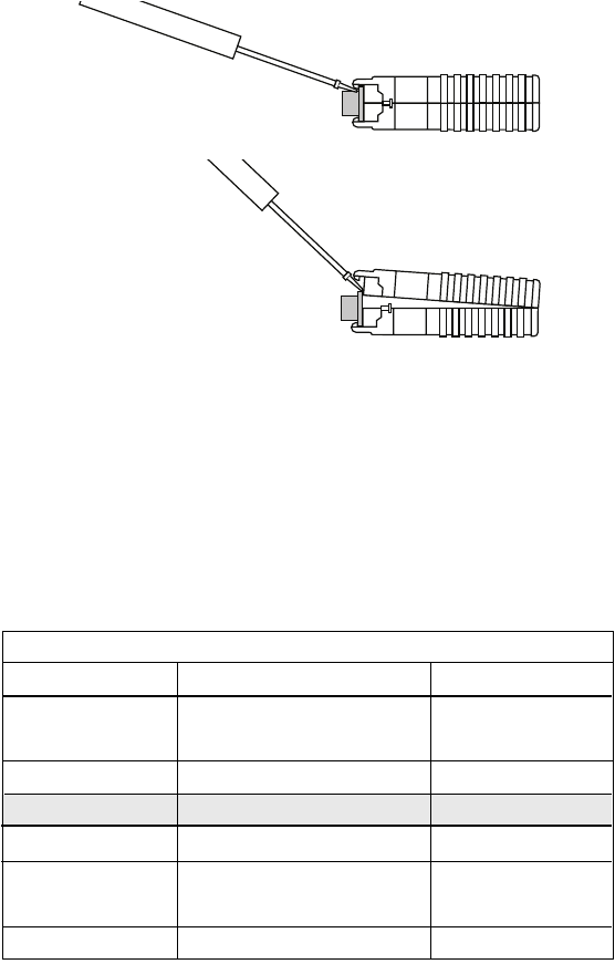
Opening the Model 1052 case
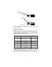
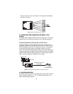
Figure 1 on page 7 shows the orientation of the DIP switches in the “ON”
and “OFF” positions.
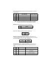
Configuring DIP Switch S1
DIP switch S1 is where you configure the data rate, asynchronous or
synchronous data format, transmit clock source. The following table sum-
marizes default positions of DIP switches S1-1 through S1-8. Detailed
descriptions of each switch follow the table.
Switches S1-1 and S1-2: Data Rate.
Use switches S1-1 and S1-2 to
configure the asynchronous or synchronous data rate of the Model 1052.
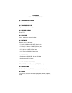
Position Function Factory Default
S1-1 Data Rate Off
S1-2 Data Rate Off
S1-3
S1-4 Reserved On
S1-5 Async/Sync Data Format Off
S1-6 Tx Clock Source On
S1-7 Tx Clock Source On
S1-8
128K Sync
}
}
Internal Clock
S1 Summary Table
Reserved On
Reserved Off