


3 4
2.0 GENERAL INFORMATION
Thank you for your purchase of this Patton Electronics product.
This product has been thoroughly inspected and tested and is warrant-
ed for One Year parts and labor. If any questions or problems arise
during installation or use of this product, please do not hesitate to con-
tact Patton Electronics Technical Support at (301) 975-1007.
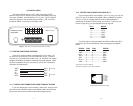
2.1 FEATURES
• Data rates to 115.2 Kbps
• Built-in optical isolation & high speed surge protection
• Distances up to 14 miles (19 AWG TWP @ 1200 bps)
• Tri-state LED indicators
• Point-to-point or multipoint
• Local and remote loopback test modes
• DCE/DTE switch selectable
• Hardware and software flow control support
• Externally powered
• Made in the U.S. A.
2.2 DESCRIPTION
The Model 1060 Series asynchronous short range modem is
equipped with a virtual wish list of “bells and whistles”: Point-to-point
or multipoint applications are supported. Two separate control signals
may be passed (one each way), each with switch-selectable pin
assignments. Data lines are protected from ground loops and electri-
cally volatile environments by optical isolation and Silicon Avalanche
Diodes. System integrity can be evaluated using two built-in test
modes: local analog loopback and remote analog loopback. Tri-state
LEDs monitor transmit data, receive data and control signals. Finally,
4-wire connections may be made using either RJ-11 jack or terminal
blocks—both are included.
In addition, the Model 1060 is perfect for low power RS-232 envi-
ronments. The new Model 1060 is AC powered, and therefore is the
recommended solution for RS-232 environments whose interface volt-
ages are below RS-232 specifications. The Model 1060 supports data
rates to 115.2 Kbps and extends RS-232 transmission distances up to
14 miles over two twisted pair.
The Model 1060 is housed in a sturdy metal case and comes with
either 115 or 220V external transformers. This is the top-of-the-line in
asynchronous short range modems.
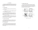
3.0 CONFIGURATION
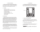
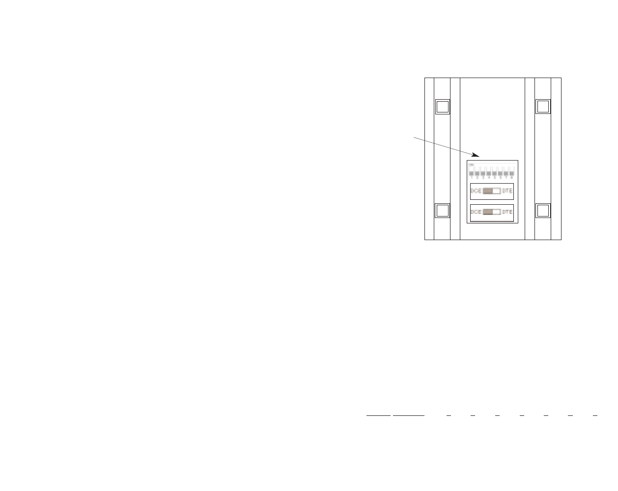
The Model 1060 features externally accessible configuration
switches, located on the underside of the unit; there is no need to open
the case to configure the Model 1060. Figure 1 (below) shows the
location of the DIP switch set, as well as the two DCE/DTE switches.
Figure 1. Switch locations underneath Model 1060
3.1 "QUICK SET-UP" INSTRUCTIONS
In the majority of applications, you won't need an in-depth knowl-
edge of the Model 1060's capabilities to get up and running. The fol-
lowing "quick set-up" DIP switch configurations cover most Model 1060
operating environments. (Note: DIP switch 8 not used)
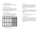
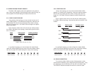
3.1.1 POINT-TO-POINT CONFIGURATION
If you are installing these units in a point-to-point application with a
computer, printer or terminal, configure the DIP switches on both
Model 1060s as follows:
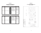
Switch Number: 1 2 3 4 5 6 7
Positions OFF OFF OFF ON ON ON OFF
DTEDCE
DTEDCE
FRONT
REAR
DIP Switches