


5.2 TEST MODES
The Model 1075 offers two V.54 test modes to evaluate the
condition of the modems and the communication link. These tests are
activated from the front panel.
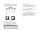
5.2.1 Local Analog Loopback (LAL)
The Local Analog Loopback (LAL) test checks the operation of the
local Model 1075, and is performed separately on each unit. Any data
sent to the local Model 1075 in this test mode will be echoed (returned)
back to the user device. For example, characters typed on the
keyboard of a terminal will appear on the terminal screen. To perform a
LAL test, follow these steps.
A. Activate LAL. This may by moving the front panel toggle
switch DOWN to LAL. Once LAL is activated, the Model 1075
transmitter output is connected to its own receiver. The test
LED should be lit.
B. Verify that the data terminal equipment is operating properly
and can be used for a test. If a fault is indicated, call a
technician or replace the unit.
C. Perform a Bit Error Rate (BER) test on each unit. If the BER
test equipment indicates no faults, but the data terminal
indicates a fault, follow the manufacturer’s checkout
procedures for the data terminal. Also, check the interface
cable between the terminal and the Model 1075.
5.2.2 Remote Digital Loopback (RDL)
The RDL test checks the performance of both the local and remote
Model 1075, and the communication link between them. Any
characters sent to the remote Model 1075 in this test mode will be
returned back to the originating device. For example, characters typed
on the keyboard of the local terminal will appear on the local terminal
screen after having been passed to the remote Model 1075 and looped
back. To perform an RDL test, follow these steps:
A. Activate RDL by moving the front panel toggle switch UP to
RDL.
B. Perform a BER test on the system.
(cont)
14
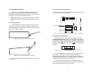
5.0 OPERATION
Once the Model 1075 is properly configured and installed, it should
operate transparently—as if it were a standard cable connection.
Section 5.0 describes the LED status monitors and the built-in V.52 and
V.54 test modes. The Model 1075 is powered by a 9V DC external wall
mount transformer. To power up the unit, connect the power supply
cord to the power jack on the rear of the Model 1075 and plug the
power adapter into the wall. There is no ON/OFF switch.
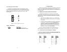
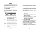
5.1 LED STATUS MONITORS
The Model 1075 features six front panel LEDs that indicate the
status of the unit and the communication link. Figure 9 shows the front
panel location of each LED. Following Figure 9 is a description of each
LEDs function.
TD (Transmit Data) Glows red to indicate an idle condition
or binary 1 data. Glows green to indicate an active
condition or binary 0 data. Glows orange to indicate
rapidly changing data. Source: DTE.
RD (Receive Data) Glows red to indicate an idle condition
or binary 1 data. Glows green to indicate an active
condition or binary 0 data. Glows orange to indicate
rapidly changing data. Source: DCE.
Control Glows green to indicate that Control from DTE is active.
Red indicates that Control from the DTE is inactive.
Indication Glows green to indicate that the Indication from DCE is
active. Red indicates that the Indication from the DCE
is inactive.
Error Glows red when errors are detected during the 511 or
511/E BER tests.
Test Glows red when the V.54 loopback test or V.52 BER
tests are initiated.
13
Model 1075
KiloModem-II
56/64K Baseband Modem
RDTD RTS CD Error Test
V.54 Test
Modes
511 -
511E -
- Remote
- Normal
- Local
(Control) (Ind)
Figure 9 - Front Panel of the Patton Model 1075