3.2 CONFIGURATION STRAPS
In addition to the configuration switches described above, the
Model 1075 is also equipped with two internal straps that set the
DTE/DCE Configuration and the DB-15 Shield. In order to configure
these straps, you must open the Model 1075 case.
NOTE: Before opening the case, determine whether the default
settings are correct for your application (see Sections 3.2.3 and
3.2.4)
3.2.1 Opening the Case
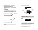
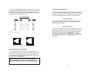
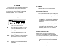
To open the Model 1075 insert a flat head screw driver into an
open slot on either side of the case, as in Figure 3. Twist the screw
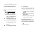
driver head slightly and the top half of the case will separate from the
lower half, as in Figure 4, below.
To close the case, fit the 2 halves together snugly and snap them
back in place.
7 8
3.2.2 Location of the Internal Straps
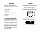
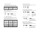
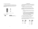
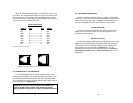
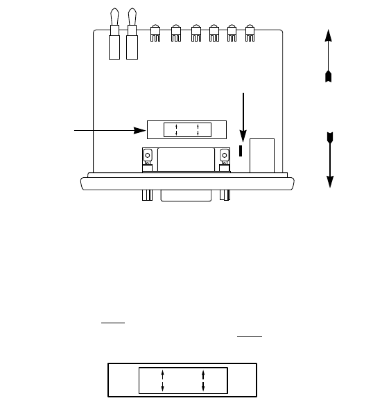
Figure 5 (below) shows the location of the DCE/DTE switch and the
JP1 strap on top side of the the PC board.
3.2.3 Setting the DCE/DTE Strap
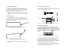
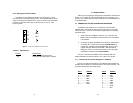
The X.21 interface on the Model 1075 is DCE/DTE switchable.
The default setting is DCE, based upon how the Model 1075 sees its
own
orientation. When configured this way, the Model 1075 will want to
connect to an X.21 DTE
device. Re-positioning the DCE/DTE strap will
enable the Model 1075 to connect to an X.21 DCE
device (See Figure
6, below).
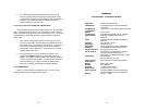
The X.21 DCE/DTE strap is located near the DB-15 connector on
the PC board. The arrows on the top of the strap indicate the
configuration of the Model 1075. For example, if the DCE arrows are
pointing toward the DB-15 Connector, the Model 1075 is configured as
a “DCE” and must connect to an X.21 DTE device.
To change the DCE/DTE orientation of the Model 1075 X.21
interface, simply remove the strap and rotate it 180
o
so the appropriate
arrows are pointing toward the DB-15 Connector.
Figure 3. Opening the 1075 Case with a Small Screwdriver
Figure 4. Opening the 1075 Case With a Small Screwdriver
Figure 5 . Position of DTE/DCE and JP1 Jumper Straps on Model 1075 PC Board
DTE
DCE
DTE/DCE Strap
Figure 6 . Close-Up of Model 1075 PC Board With Close-up of DCE/DTE Strap
Default Setting = “DCE”
DTE
DCE
JP1 Strap
Front
Rear


