


14
4.0 INSTALLATION
Once the Model 1088/K is properly configured, it is ready to connect to
the twisted pair interface, to the serial port, and to the power source. This
section describes how to make these connections.
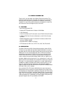
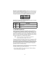
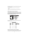
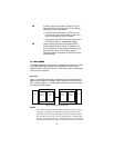
4.1 CONNECT G.703 NETWORK
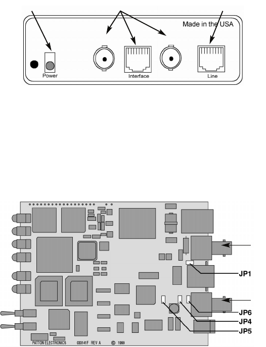
The Power, G.703/G.704 and DSL Line connections are located on the
rear panel of the Model 1088/K. Figure 4 shows the location of each of
these ports.
Figure 4.
Model 1088/K Rear Panel
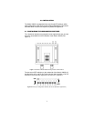
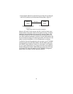
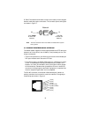
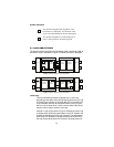
4.2 JUMPER CONFIGURATION
The Model 1088/K has four jumpers (two position headers): JP1, JP4,
JP5, and JP6. These jumpers are used to select input or output imped-
ance matching between the module, external line, and to employ either
BNC or RJ-48C interface. Figure 5 (below) shows the top view of the
printed circuit board (PCB) and the location of the jumpers.
Figure 5.
Top view of 1088/K, location of JP1, JP4, JP5, and JP6
G.703/G.704 Terminations DSL LinePower
RX
TX
RX
TX