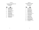
APPENDIX D
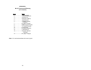
DB-15F Connector-DCE Setting
(X.21 Interface)
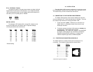
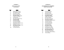
Pin # Signal
1. . . . . . . . . . . . Frame Ground
2. . . . . . . . . . . . T (Transmit Data-A)
3. . . . . . . . . . . . C (Control-A)
4. . . . . . . . . . . . R (Receive Data-A)
5. . . . . . . . . . . . I (Indication-A)
6. . . . . . . . . . . . S (Signal Element
Timing-A)
7. . . . . . . . . . . . BT (Byte Timing-A)
8. . . . . . . . . . . . SGND (Signal Ground)
9. . . . . . . . . . . . T/ (Transmit Data-B)
10. . . . . . . . . . . C/ (Control-B)
11. . . . . . . . . . . . R/ (Receive Data-B)
12. . . . . . . . . . . I/ (Indication-B)
13........................S/ (Signal Element
Timing-B)
14.......................BT/ (Byte Timing-B)
Note: X.21 uses balanced data and control signals.
25


