


Planning the Installation 16
CopperLink 1211E/1212E User Manual 2 • Installation
Planning the Installation
CAUTION
The Interconnecting cables shall be acceptable for external use
and shall be rated for the proper application with respect to volt-
age, current, anticipated temper
ature, flammability, and
mechanical serviceability.
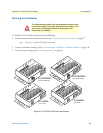
To install the CL1212E Ethernet Extender, do the following:
1. Conn
ect the line interface between the units (refer to “Connecting the Line Interface” on page 17)
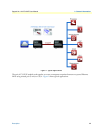
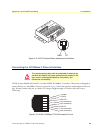
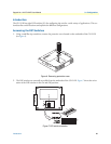
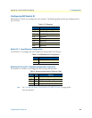
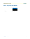
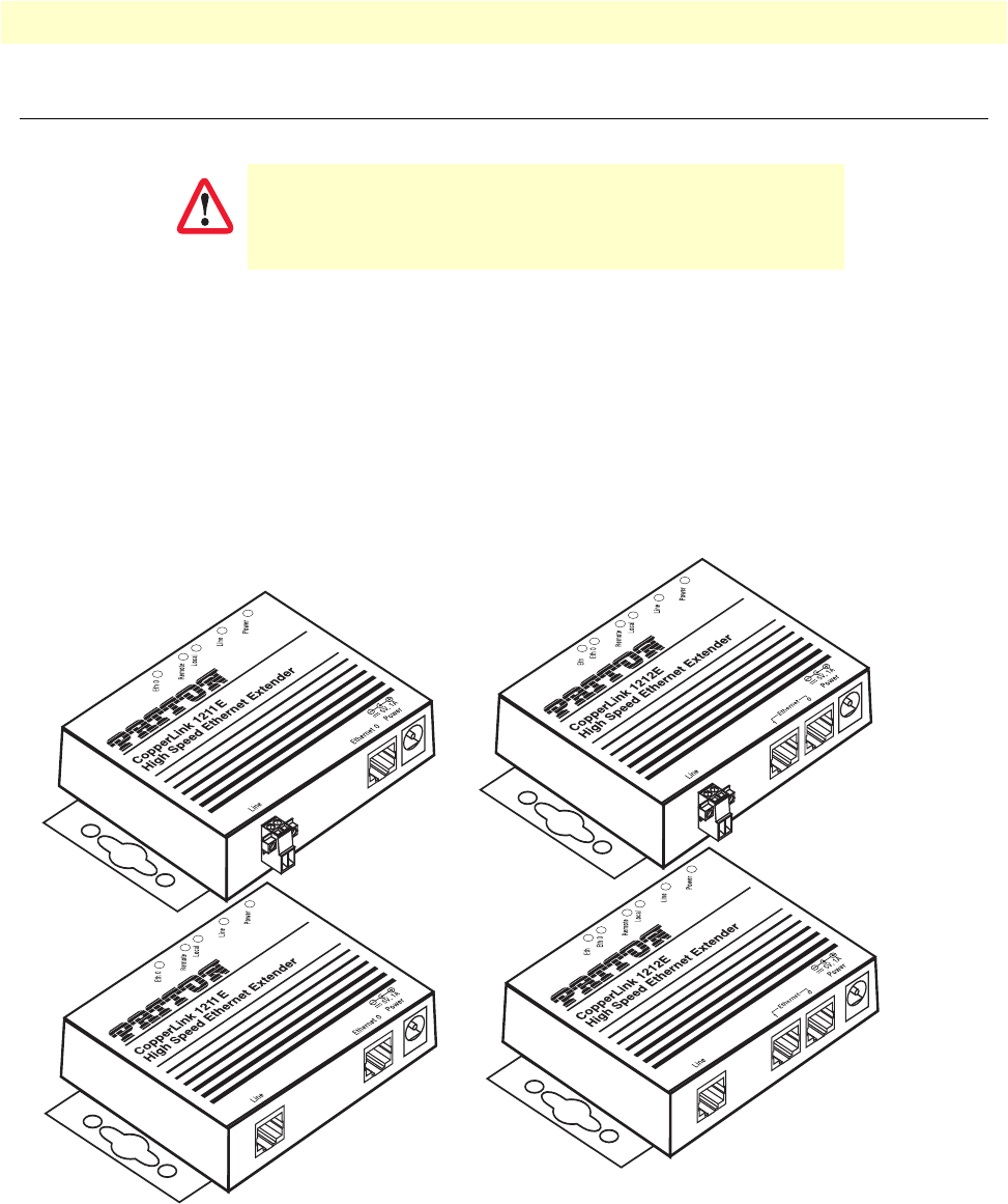
Note See figure 2 for the CL1212E’s rear panel.
2. Conn
ect the Ethernet interface (refer to “Connecting the 10/100Base-T Ethernet Interface” on page 18).
3. Conn
ect the power plug (refer to “Connecting Power” on page 19).
S
Figure 2. CL1211E/CL1212E rear panel options
1
1
CL1211E/TB/EUI
(Line: Terminal Block)
CL1212E/TB/EUI
(Line: Terminal Block)
CL1212E/EUI
(Line: RJ-45)
CL1211E/EUI
(Line: RJ-45)