


Configuring DIP Switch S1 22
CopperLink 1211E/1212E User Manual 3 • Configuration
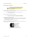
Configuring DIP Switch S1
DIP switch S1 is where you configure the Line interface. The following tables describe the configuration for
the CL1212E.
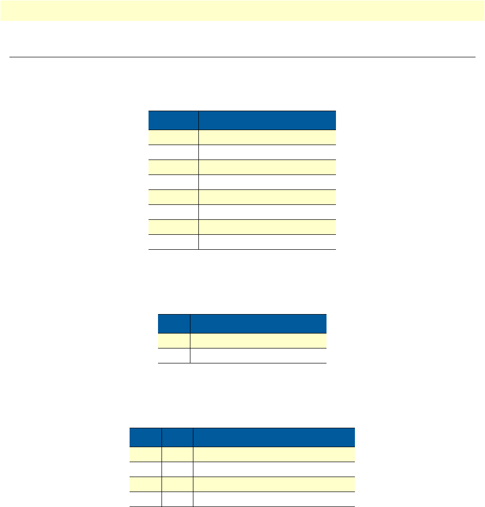
Table 1. S1 Summary
Position Description
S1-1 Local/Remote Configuration
S1-2 Line Rate/Symmetry
S1-3 Line Rate/Symmetry
S1-4 Reserved
S1-5 SNR Margin
S1-6 Reserved
S1-7 Reserved
S1-8 Reserved
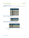
Switch S1-1: Local/Remote Configuration
Use switch S1-1 to configure the unit as Remote or Local in the CL1212E pair.
Table 2. Local/Remote Unit Configuration
S1-1 Setting
ON CPE/Remote
OFF CO/Local
Switches S1-2 and S1-3: Symmetric/Asymmetric Operation
Use switches S1-2 and S1-3 to configur
e the line rate type and operation.
Table 3. Symmetric/Asymmetric Selection Chart
S1-2 S1-3 Setting
OFF OFF High-Speed “Symmetric”
OFF ON High-Speed “Asymmetric”
ON OFF FastPath High-Speed “Asymmetric”
ON ON Long-Range “Asymmetric”
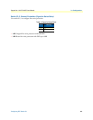
Note
See “Line Rate & Reach Chart Based on 24 AWG (0.5 mm)” on page 39 for
line rate distances.