


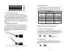
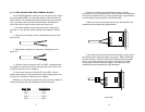

4.2.2 DAISY CHAIN TOPOLOGY
Using a daisy chain topology, you may connect several Model
2085s together in a master/slave arrangement. Maximum distance
between the units will vary based upon the number of drops, data rate,
wire gauge, etc. Call Technical Support for specific distance estimates.
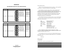
Figure 8 (below) shows how to wire the two-pair cables properly for
a Model 2085 daisy chain topology. Note that the ground connection is
not needed.
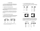
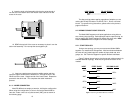
4.3 CONNECTION TO THE RS-232 INTERFACE
Once you have properly configured the Model 2085 and connected
the twisted pair wires correctly, simply plug the Model 2085 directly into
the DB-25 port of the RS-232 device. Remember to insert and tighten
the two captive connector screws.
(Note: If you must use a cable to connect the Model 2085 to the
RS-232 device, make sure it is a
straight through
cable of the shortest
possible length—we recommend 6 feet or less).
4.4 OPERATING THE MODEL 2085
Once the Model 2085 is properly installed, it should operate
transparently—as if it were a standard cable connection. Operating
power is derived from the RS-232 data and control signals; there is no
“ON/OFF” switch. All data signals from the RS-232 and RS-485
interfaces are passed straight through. Additionally, one hardware flow
control signal is passed
in each direction
.
APPENDIX A
PATTON MODEL 2085 SPECIFICATIONS
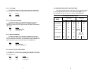
Transmission
Format: Asynchronous
Data Rate: Up to 115,200 bps
Range: Up to 9 miles
RS-232 Interface: DB-25, male or female (DCE/DTE
switchable)
RS-485 Interface
Options: DB-25, male or female; RJ-11 or RJ-45 jack;
terminal block with strain relief
Transmit Line: 2, 4 wire unconditioned twisted pair
Transmit Mode: 4-wire, full or half duplex; 2-wire half duplex
Control Signals: DSR turns “ON” immediately after the
terminal raises DTR; DCD turns “ON” after
recognizing the receive signal from the line;
CTS turns “ON” after the terminal raises
RTS.
RTS/CTS Delay: 8 mSec or “no delay”
Carrier: The carrier is switch selected either
continuous operation or switched operation,
controlled by RTS
Surge Protection: 600W power dissipation at 1 mS
Power: Draws operating power from RS-232 data
and control signals; no AC power or
batteries required.
Temperature: 0 to 50º C
Humidity: 5 to 95%, non-condensing
Size: 2.66” x 2.10” x 0.73”
15 16
HOST FIRST SLAVE OTHER SLAVE(S)
XMT+---------------------RCV+-----------------------RCV+
XMT- ---------------------RCV- -----------------------RCV-
RCV+---------------------XMT+-----------------------XMT+
RCV- ---------------------XMT- -----------------------XMT-
Figure 8. Daisy chain wiring for Model 2085 host and slaves