


19 20
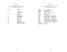
APPENDIX E
X.21 Terminal Interface Pin Assignment
(DB-15 Male Connector)
Pin # Signal
1 Frame GND
2 Transmilt A
3 Control A
4 Receive A
5 Indication A
6 Signal Timing A
8 Signal GND
9 Transmit B
10 Control B
11 Receive B
12 Indication B
13 Signal Timing B
14 DC Power (+5VDC)
15 DC Power (+5VDC)
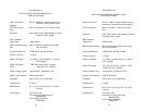
APPENDIX F
V.35 Terminal Interface Pin Assignment
(M/34 Male Connector)
Pin # Signal
A GND (Earth Ground/Shield)
B SGND (Signal Ground)
D CTS (DCE Source)
E DSR (DCE Source, Always On)
F CD (DCE Source)
H (DTR) (DTE Source)
P TD (Transmit Data +, DTE Source)
R RD (Receive Data +, DCE Source)
S TD/ (Transmit Data -, DTE Source)
T RD/ (Receive Data -, DCE Source)
V RC (Receiver Clock +, DCE Source)
X RC/ (Receiver Clock -, DCE Source)
Y TC (Transmitter Clock +, DCE Source)
AA TC/ (Transmitter Clock -, DCE Source)
KK (Power)(+5VDC)
NN (Power)(+5VDC)