


7
4.3 POWER CONNECTION
The Model 2121/2135C offers either an AC or DC power sup-
ply.
The 2121/2135C provides a strap selectable power supply.
4.3.1 AC Power Supply (100-240VAC)
The Model 2121/2135C uses a 5VDC, 2A universal input 100-
240VAC, power supply (center pin is +5V). The universal input
power supply is equipped with a male IEC-320 connector. This
power supply connects to the Model 2121/2135C via a barrel jack
on the rear panel. A variety of international power cords are avail-
able for the universal power supply.
The Model 2121/2135C powers up as soon as it is plugged
into an AC outlet. The unit does not have a power switch.
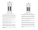
The 2121/2135C is factory set to be used with the AC power
supply.
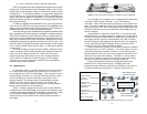
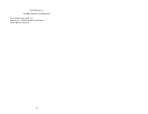
Note: Default setting has strap on position 7 and 8 on J3 for
AC power supply. See figure 4 below.
4.0 INSTALLATION
The 2121/2135C is equipped with Network, DTE, and power
interfaces. This section briefly describes connnection to each inter-
face.
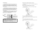
4.1 CONNECT TO 10BASET ETHERNET PORT
The shielded RJ-45 Ethernet port on the Model 2121/2135C is
designed to connect directly to a 10BaseT network. Figure 3
shows the 10BaseT RJ-45 port pin description. You may make
connections up to 300 feet using type 4 or 5 cable.
4.1.1 Connect the 10BaseT Ethernet Port to a Hub
The Model 2121/2135C 10BaseT interface is configured as
DTE (Data Terminal Equipment). Use the diagram below to con-
struct a cable to connect the 2121/2135C to a 10BaseT Hub.
2121/2135C 10BaseT Hub
RJ-45 Pin No. RJ-45 Pin No.
1 (TX+)..........................1 (RX+)
2 (TX-)..........................2 (RX-)
3 (RX+).........................3 (TX+)
6 (RX-)..........................6 (TX-)
4.1.2 Connect the 10BaseT Ethernet Port to a PC (DTE)
The Model 2121/2135C 10BaseT interface is configured as
DTE (Data Terminal Equipment). To connect the 2121/2135C to
another DTE such as a 10BaseT network interface card in a PC,
construct a 10BaseT crossover cable as shown in the diagram
below.
2121/2135C 10BaseT DTE
RJ-45 Pin No. RJ-45 Pin No.
1 (TX+) 1 (TX+)
2 (TX-) 2 (TX-)
3 (RX+) 3 (RX+)
6 (RX-) 6 (RX-)
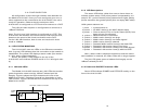
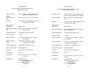
1 TD+ (data output from Ethernet)
2 TD- (data output from Ethernet)
3 RD+ (data input to Ethernet)
4 (no connection)
5 (no connection)
6 RD- (data input to Ethernet)
7 (no connection)
8 (no connection)
Figure 3.
Model 2121/2135C Ethernet connector pinout
8
Figure 4.Strap positions 7 and 8 on J3