


8
Follow the steps below to connect the CopperLink interfaces.
Note
The Model 2156 or 2157 units work in pairs. One of the units
must be a Model 2156/L (local) or 2157/L, and the other unit
must be a Model 2156/R (remote) or 2157/R.
1. To function properly, the two Ethernet Extenders must be connected
together using twisted-pair, unconditioned, dry, metal wire, between
19 (0.9mm) and 26 AWG (0.4mm). Leased circuits that run through
signal equalization equipment are not acceptable.
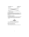
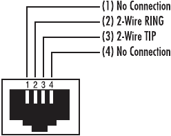
2. The Models 2156 and 2157 are equipped with an RJ-11 interface.
The CopperLink interfaces are a two-wire interface. Observe the sig-
nal/pin relationships on the CopperLink interface jack.
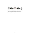
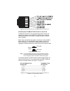
The RJ-11 connector on the CopperLink Ethernet Extender’s twisted pair
interface is polarity insensitive and is wired for a two-wire interface. The
signal/pin relationship is shown in Figure 3.
Figure 3.
CopperLink Ethernet Extender (RJ-11) twisted pair line interface.
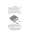
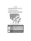
3.2 LINE INTERFACE—CONNECTING THE 10/100BASE-T
ETHERNET INTERFACE
The shielded RJ-45 port labeled
Ethernet
is the 10/100Base-T interface.
This port is designed to connect directly to a 10/100Base-T network.
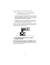
Figure 4 shows the signal/pin relationships on this interface. You may
connect this port to another Ethernet device via a Type 4 or Type 5 cable
that is up to 328 ft (100 m) long.