


9
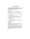
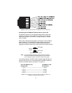
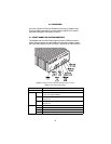
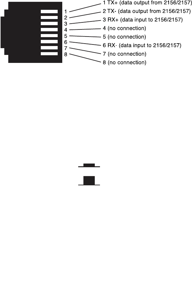
Figure 4.
CopperLink Ethernet Extender 10/100Base-T RJ-45 Connector Pinout.
Connecting the 10/100Base-T Ethernet Port to a Hub or PC
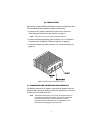
The Models 2156 and 2157 are equipped with an MDI-X switch that
enables connections to a hub (DCE) or PC (DTE) interface, thereby
elimininating confusion over whether a straight-through or crossover
cable is needed.
When using a straight-through cable for connecting to a hub, the MDI-X
switch should be in its released (DCE mode) position (see Figure 5).
When connecting to a PC, the MDI-X switch should be pushed in to
engage the crossover function so you won’t have to use a crossover cable
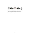
Figure 5.
MDI-X switch positions
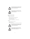
Note
If you have difficulty achieving a working connection between
the CopperLink Ethernet Extender’s Ethernet port and the hub
or PC, change the position of the MDI-X switch and try again.
In its released position, the MDI-X switch enables straight-through con-
nections (see Figure 6) or in its inserted position the MDI-X switch per-
forms the crossover function (see Figure 7 on page 10).
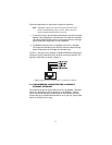
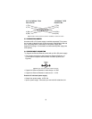
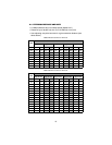
Figure 6.
Wiring diagram for connecting the CopperLink Ethernet Extender to a
10/100Base-T hub (MDI-X switch released)
DCE mode
MDI-X
switch
DTE mode
2157 10/100Base-T Port
RJ-45 Pin No.
10/100Base-T Hub
RJ-45 Pin No.
1 (TX+)--------------------------------------------------1 (RX+)
2 (TX-)---------------------------------------------------2 (RX-)
3 (RX+)--------------------------------------------------3 (TX+)
6 (RX-)---------------------------------------------------6 (TX-)