


17
5.0 OPERATION
When the Model 2701 has been properly configured and installed, it
should operate transparently. This sections describes power-up, LED
status monitors, and the built-in loopback test modes.
5.1 POWER-UP
Before applying power to the Model 2701, please read “Power Connec-
tion” on page 15 and verify that the unit is properly connected to the
appropriate power source.
5.2 LED STATUS MONITORS
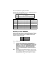
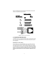
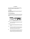
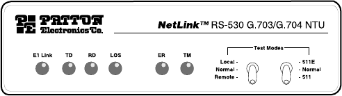
The Model 2701 features six front panel LEDs that monitor connections
on the G.703/G.704 and signaling, error and test modes. Figure 6 shows
the front panel location of each LED. Descriptions of each LED follow
Figure 6.
Figure 6.
2701 Front Panel
E1 Link
(Active Green) Solid green (On) indicates that the end to end E1
Link is up, signifying that the link is active. The E1 Link LED is
Off when the link is down.
TD & RD
Glows yellow to indicate an idle condition of Binary “1” data on
the respective terminal interface signals. Green indicates Binary
“0” data.
LOS
The Loss of Sync LED lights when the unit loses synchroniza-
tion with the incoming signal. This may happen when there is a
framing mismatch or a loss of signal. In unframed mode, the
LOS LED monitors the status of the transmit clock.
ER
The error LED indicates various error conditions, including fram-
ing bit errors, excessive zeros, controlled slips, severe errors, or
bit errors (when sending V.52 test patterns). When sending a
test pattern, the LED will remain lit if the unit does not receive