


7
3.0 CONFIGURATION
The Model 2701 features configuration capability via hardware DIP
switches. This section describes all possible DIP switch configurations of
the Model 2701.
3.1 DIP SWITCH CONFIGURATION
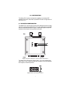
The Model 2701 has two sets of internal DIP switches that allow configu-
ration for a wide range of applications. The sets of switches are accessed
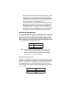
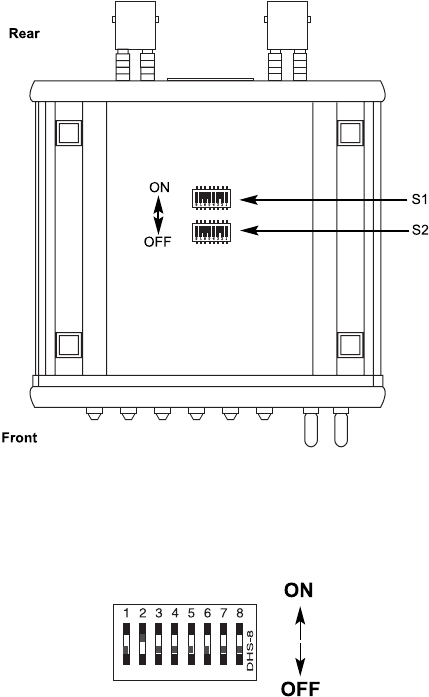
from the underside of the 2701. Figure 1 shows the location of the DIP
switches on the bottom of the printed circuit board.
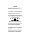
Figure 1.
Underside of Model 2701, Showing Location of DIP Switches
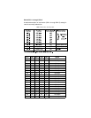
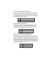
The Model 2701 DIP switches (Switch Sets 1–2) can be configured as
either “ON” or “OFF”. Figure 2 shows the orientation of the DIP switches
with respect to ON/OFF positions.
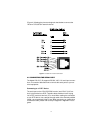
Figure 2.
Close up of configuration switches