


SmartNode Model 4830 Series Overview 22
SmartNode 4830 Getting Started Guide 1 • General information
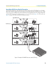
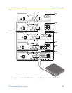
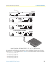
Ports descriptions
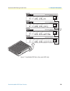
The SmartNode 4830 Series rear-panel ports are described in table 2.
Reset button behavior
For those SmartNode devices that have a Reset button on the rear panel, its behavior is as follows:
• To restart the unit with the current startup configuration—Press for less than 1 second and release the Reset
button. The SmartNode will restart with the current startup configuration.
• To restart the unit with factory default configuration—Press the Reset button for 5 seconds until the Power
LED starts blinking. The unit will restart with factory default configuration.
• To restart the unit in bootloader mode (to be used only by trained SmartNode technicians)—Start with the
unit powered off. Press and hold the Reset button while applying power to the unit. Release the Reset button
when the Power LED starts blinking so the unit will enter bootloader mode.
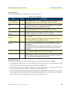
Table 2. Rear panel ports
Port Location Description
10/100 Ethernet
ETH 0/0 & ETH 0/1
Rear panel
RJ-45 connectors (see figure 3 on page 18) that connect the product to an
Ethernet device (e.g., a cable or DSL modem, LAN hub or switch).
Analog voice port,
FXS
Rear panel
FXS RJ-11(6 position, 4 wire) connectors (see figure 3 on page 18) that
connect the product with an analog terminal (a telephone, for example)
FXO port. EuroPOTS support (ETSI EG201 188).
Analog voice port,
FXO
Rear panel FXO RJ-11(6 position, 4 wire) connectors that connect the product with an
analog line (FXS port). EuroPOTS support (ETSI EG201 188).
V.35 or X. 21 Serial
(option)
Rear Panel Female DB-25 or DB-15 socket provides a V.35 or X.21 serial interface for
leased-line connection to a WAN at rates up to 2 Mbps.
T1/E1
(option)
Rear panel
E1—G.703/G.704 with HDB3 or AMI encoding. RJ-48C and dual coax-
ial connectors.
T1—ANSI T1.403 & AT&T TR54016 with AMI coding/D4 framing or
B8ZS coding/ESF framing. RJ-48C connector.
G.SHDSL/ADSL port
(option)
Rear panel Provides up to 5.7 Mbps (G.SHDSL) or 8 Mbps (ADSL) symmetrical
throughput, supporting ATM QoS. Supports multiple PVC and DSLAM
interoperability.
The DSL LEDs are located on either side of the DSL port. ACT (when lit or
blinking) shows Activity, and LINK (when lit) shows that the DSL port is
connected.
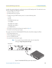
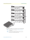
Power Rear panel The gateway is available in a DC or AC power input version (see
figure 6), labeled
100–240 VAC, 50/60 Hz, 200 mA
Console Front panel
Used for service and maintenance, the Console port (see figure 7 on page 23),
an RS-232 RJ-45 connector, connects the product to a serial terminal such as a
PC or ASCII terminal (also called a dumb terminal).