


1. Configure IP address 45
SmartNode 4830 Getting Started Guide 4 • Getting started with the SmartNode
1. Configure IP address
Power connection and default configuration
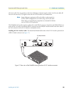
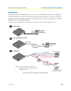
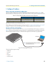
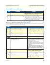
The factory default configuration for the Ethernet IP addresses and network masks are listed in table 10. Both
Ethernet interfaces are activated upon power-up. LAN interface ETH 0/1 (LAN) provides a default DHCP server.
Both Ethernet interfaces are activated upon power-up.
If these addresses match with those of your network, go to section “2. Connect the SmartNode to the network”
on page 47. Otherwise, refer to the following sections to change the addresses and network masks.
Connect with the serial interface
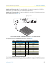
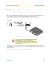
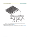
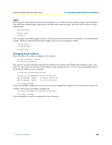
The Console port is wired as an EIA-561, RS-232 port. Use the included Model 16F-561 adapter and cable (see
figure 24) between the SmartNode’s Console port and a PC or workstation’s RS-232 serial interface. Activate the
terminal emulation program on the PC or workstation that supports the serial interface (e.g. HyperTerm).
Figure 24. Connecting to the terminal
Terminal emulation program settings:
• 9600 baud
• no parity
• 8 bit
• 1 stop bit
• No flow control
Table 10. Factory default IP address and network mask configuration
IP Address Network Mask
WAN interface Ethernet 0 (ETH 0/0) DHCP DHCP
LAN interface Ethernet 1 (ETH 0/1) 192.168.1.1 255.255.255.0
DHCP address range 192.168.1.10–192.168.1.19 255.255.255.0
Serial Terminal
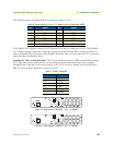
Note
A Patton Model 16F-561 RJ45 to DB-9 adapter is included with
each SmartNode 4000 Series device
Console
VoIP Gateway Router
ToIP Integrated Access Device
SmartNode 4524
Link
100M
Activity
0/0
0/1
0/2
0/3
Enet 0 Voice Ports
Power
Run
VoIP Link
Link
100M
Activity
Enet 1