


SmartNode 4900 Series detailed description 18
SmartNode 4900 User Manual 1 • General information
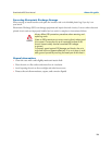
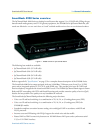
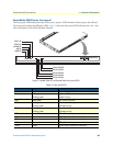
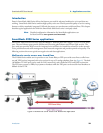
SmartNode 4900 Series
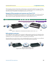
front panel
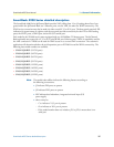
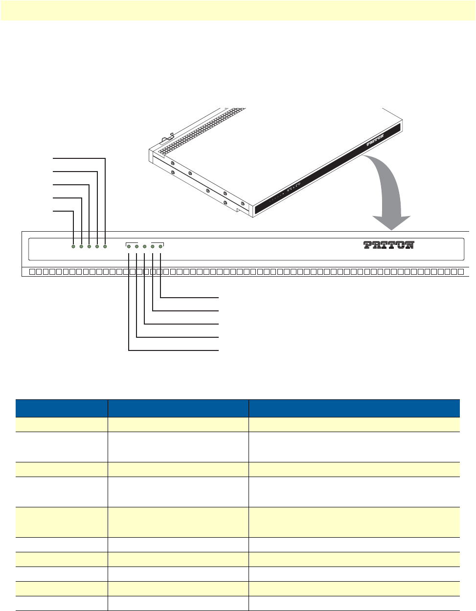
The front panel LEDs display the status of the power, system, VOIP channels, Ethernet ports, and call load.
The front panel includes the following LEDs. Figure 2 shows the front panel LED indicators and table 2 pro-
vides a description of the LED indicators’ behavior.
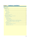
Figure 2. Model SN4932 IpChannel Bank front panel LEDs.
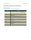
Table 2. Front panel LEDs
LED LED Condition Description
Power Solid Green Power is applied
Run Solid green
Blinking green
System is idle.
System is busy.
VoIP Solid green VoIP ports are active
ETH0 Solid green
Blinking green
Ethernet Port 0 is up
Indicates activity
ETH1 Solid green
Blinking green
Ethernet Port 1 is up
Indicates activity
20% Green 20% of the voice ports are active
40% Green 40% of the voice ports are active
60% Green 60% of the voice ports are active
80% Green 80% of the voice ports are active
100% Green 100% of the voice ports are active
UNIT EQUIPPED WITH DUAL SUPPLIES
D
ISCONNECT BOTH SUPPLIES
BEFORE SERVICIN
G
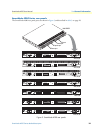
ToIP Integrated Access Device
Ip
C
h
an
n
e
l B
a
nk
VOIP LINK
ETH 0/0
ETH 0/1
RUN
ETH 0/1
POWER
100%80%60%40%20%
CALL LOAD
ToIP Integrated Access Device
IpChannel Bank
VOIP LINK
ETH 0/0
ETH 0/1
RUN
POWER
20% CALL LOAD LED
40% CALL LOAD LED
60% CALL LOAD LED
100% CALL LOAD LED
80% CALL LOAD LED
ETH 0/1 LED
ETH 0/0 LED
VOIP LINK LED
RUN LED
POWER LED
100%80%60%40%20%
CALL LOAD