


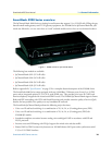
SmartNode 4900 Series detailed description 20
SmartNode 4900 User Manual 1 • General information
Reset button behavior
For those SmartNode devices that have a Reset button on the rear panel, its behavior is as follows:
• To restart the unit with the current startup configuration—Press for less than 1 second and release the Reset
button. The SmartNode will restart with the current startup configuration.
• To restart the unit with factory default configuration—Press the Reset button for 5 seconds until the Power
LED starts blinking. The unit will restart with factory default configuration.
• To restart the unit in bootloader mode (to be used only by trained SmartNode technicians)—Start with the
unit powered off. Press and hold the Reset button while applying power to the unit. Release the Reset button
when the Power LED starts blinking so the unit will enter bootloader mode.
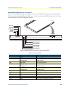
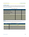
Table 3. Port descriptions
Port Description
ETH 0/0 (WAN Ethernet 0/0 port) 10/100Base-Tx full-/half-duplex, RJ-45, auto detection and auto-
MDI-X connects the unit to an Ethernet WAN device (for example,
a cable modem, DSL modem, or fiber modem).
ETH 0/1 (LAN Ethernet 0/1 port) 10/100Base-Tx full-/half-duplex, RJ-45, auto detection and fall-
back, connects the unit to an Ethernet LAN.
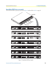
Expansion
•
V.35 serial port—DB-25 connector, data rates up to 2 Mbps,
Frame Relay or PPP protocols, Status and Activity
LED indicators, configured as DTE
•
X.21 serial port—DB-15 connector, data rates up to 2 Mbps,
Frame Relay or PPP protocols, Status and Activity
LED indicators, configured as DTE
Console (RS-232 control port) Used for service and maintenance, the Console port, an RS-232
RJ-45 connector with EIA-561 pinout, connects the router to a
serial terminal such as a PC or ASCII terminal (also called a dumb
terminal). Asynchronous default data rate 9600 bps, hardware
DSR and DTR signals for external modems are wired directly
together internally
FXS Ports (4900/JS models) For connection of up to 32 analog FXS devices (selectable for 12,
16, 24, or 32). Either a 50-pin or 64-pin RJ21X connector that
connects the router to an analog terminal (a telephone, for exam-
ple) FXO port. EuroPOTS support (ETSI EG201 188).
FXO Ports (4900/JO models) For connection of up to 32 analog FXO devices (selectable for
12, 16, 24, or 32). FXO RJ-11(6 position, 4 wire) connectors that
connect the product with an analog line (FXS port). EuroPOTS sup-
port (ETSI EG201 188).
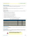
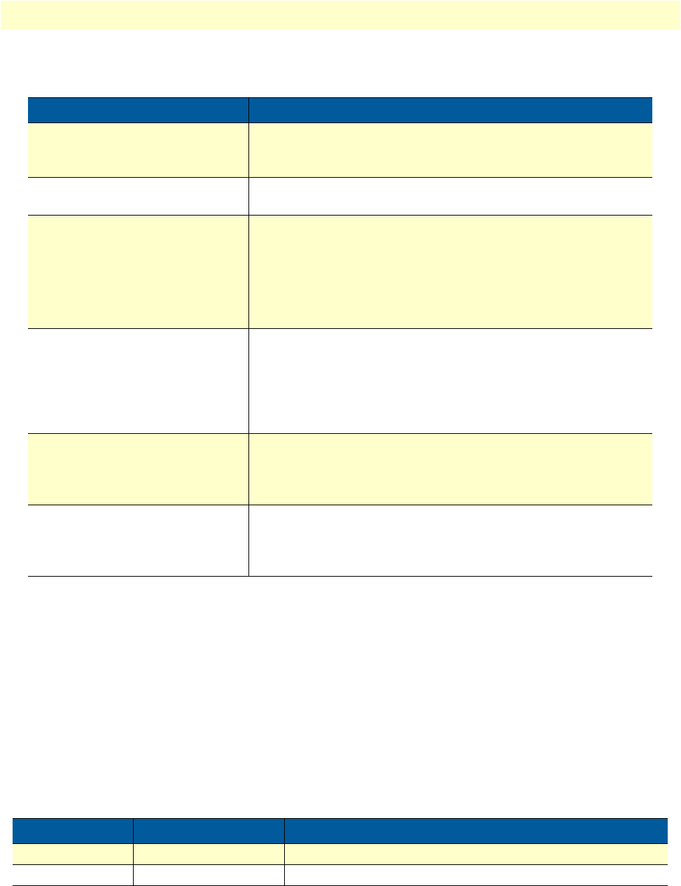
Table 4. Rear panel expansion port LED descriptions
LED Indication Description
Status Solid yellow Proper signals are present for modem communication
Activity Flashing yellow Transmit or receive traffic is present on the serial interface