


11 12
4.1.2 2-Wire Connection Using RJ-45
Most RS-485 devices employ a two-wire, half duplex configuration.
When using this configuration, be sure to first set the Model 593/45 to
half duplex mode by switching DIP switches and jumpers (refer to sec-
tion 3.0 for this configuration)—then use
only the transmit (XMT) pair
as shown below
593/45
SIGNAL RS-485 SIGNAL
XMT+....................................+
XMT-.....................................-
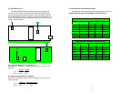
4.1.3 4-Wire Connection Using Terminal Blocks
If you purchased the Model 593/TB, you will need to open the
case to access the terminal blocks. The following instructions will tell
you how to open the case, connect the bare wires to the terminal
blocks, and fasten the strain relief collar in place so that the wires
won't pull loose.
1. If the case is not already open, open it now by twisting it open
with a small plastic screwdriver.
2. Strip the outer insulation from the twisted pairs about one inch
from the end.
3. Strip back the insulation on each of the 2 twisted pair wires
about .25 inch.
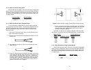
4. Place the cable through the end plate, and make a small loop
in the cable and feed the cable under the tie wrap which is cur-
rently installed in the board. When you have completed this
assembly it should resemble figure figure 5. Connect
one pair
of wires to XMT+ and XMT- (transmit positive and negative)
on the terminal block, making careful note of which color is
positive, and which color is negative.
5. If you are using 4-wire mode, connect the other pair of wires to
RCV+ and RCV- (receive positive and negative) on both of the
terminal blocks, again making careful note of which color is
positive, and which is negative.
Ultimately, you will want to construct a four pair cross over cable
that makes a connection with the RS-422/485 device, as shown below.
Model
593/TB RS-422/-485 Device
SIGNAL TERMINAL BLOCK SIGNAL
TXB+ TB (5) RXB+
TXA- TB (4) RXA-
RXB+ TB (1) TXB+
RXA- TB (2) TXA-
4.1.4 2-Wire Connection Using Terminal Blocks
Most RS-485 devices employ a two-wire, half duplex configuration.
When using this configuration, be sure to first set the Model 593/TB to
half duplex mode by switching DIP switches and jumpers (refer to sec-
tion 3.0 for this configuration)—then use
only the transmit (XMT) pair
as shown below
Model
593/TB RS-485 Device
XMT+ .......................... +
XMT- ............................ -
Figure 5. Model 593/TB, showing Terminal Block & Cable Routing