


13 14
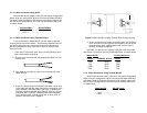
4.1.5 4-Wire Connection Using DB-25
Most DB-25 connectors on the Model 593/25F conform to EIA-530
interface standards. When connecting to the RS-422/485 devices
which also conform to EIA-530 standards, your cable should have
crossed over wiring, as shown below.
Model 593/TB
RS-485
SIGNAL DB-25 PIN DB-25 PIN SIGNAL
TXA+ 2 3 RXA+
TXB- 14 16 RXB-
RXA+ 3 2 TXA+
RXB- 16 14 TXB-
4.1.6 2-Wire Connection Using DB-25
Most DB-25 connectors on the Model 593/25F conform to EIA-530
interfaces standards. The RS-422/485 devices also conform to EIA-530
requirements and when connecting these devices, follow the wiring
shown below.
Model 593/25F
RS-485
SIGNAL DB-25 PIN SIGNAL
TXA 2 +
TXB 14 -
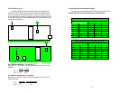
4.2 OPERATING THE MODELS 593 SERIES
Once the Models 593/25F, 593/45, and 593/TB are properly configured
and installed, it should operate transparently
___
as if it were a standard cable con-
nection. Plug in the external power supply and the units will be powered up.
APPENDIX A
PATTON ELECTRONICS MODEL 593/25, 593/45, and 593/TB
SPECIFICATIONS
Transmission Format: Asynchronous, full or half duplex
Interface Standard: RS-422/RS-485
Connectors: Model 593/25F; DB-25 female on
both sides
Model 593/45; RJ-45 on both sides
Model 593/TB; Terminal block on
both sides
Data Rates: Up to 115.2 kbps
Power Supply: External wall-mount transformer,
Regulated +5 VDC @ 120mA
Isolation: 2500 Vrms/optical Isolation
Dimensions: Model 593/45 & 593/TB
3.8”L x 2.1”W x 0.79”H
Model 593/25
4.1”L x 2.1”W x 0.79H
Temperature Range: 0-60
°
C (32-140
°
F)
Altitude: 0-10,100 feet
Humidity: 5 to 95% noncondensing