


11
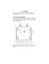
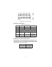
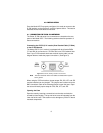
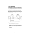
The DCE/DTE strap is located near the DB15 connector on the top side
of the board. The arrows on the top of the strap indicate the configura-
tion of the X.21 port (for example, if the DCE arrows are pointing toward
the DB-15 connector, the X.21 port is wired as a DCE). Reverse the
DCE/DTE orientation by pulling the strap out of its socket, rotating it
180º, then plugging the strap back into the socket. You will see that the
DCE/DTE arrows now point in the opposite directions, showing the new
configuration of the X.21 port.
Note
If the 2707/D is configured as a DTE, the clocking mode must
be set for external clock.
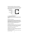
4.3 POWER CONNECTION
Universal AC Power (100-240VAC)
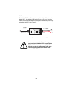
The Model 2707 uses a 5VDC, 2A universal input 100-240VAC, power
supply (center pin is +5V). The universal input power supply has a male
IEC-320 power entry connector. This power supply connects to the
Model 2707 by means of a barrel jack on the rear panel. Many interna-
tional power cords are available for the universal power supply.
The Model 2707 powers up as soon as it is plugged into an AC outlet--
there is no power switch.