


1
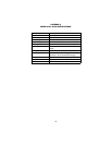
TABLE OF CONTENTS
1.0 Warranty Information ................................................................. 2
1.1 FCC Information ........................................................................... 2
1.2 CE Notice...................................................................................... 2
1.3 Service.......................................................................................... 3
2.0 General Information.................................................................... 4
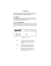
2.1 Features........................................................................................ 4
2.2 Description.................................................................................... 4
3.0 Configuration .............................................................................. 5
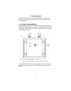
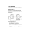
3.1 DIP Switch Configuration.............................................................. 5
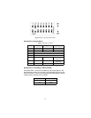
Switch SW1-1 through SW1-8...................................................... 6
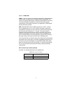
Switch SW1-1 Line Coding: HDB3 (default)............................... 6
SW1-2 Local Loop: Inactive (default) ........................................... 7
SW1-6 and SW1-7 Clock Modes.................................................. 8
SW1-8: Enable/Disable Loop Tests from DTE ............................. 8
4.0 Installation................................................................................... 9
4.1 Connecting To The G.703 Network .............................................. 9
Connecting the 2707/D (X.21 version) Dual
Coaxial Cable (75 Ohm) to the G.703 Network............................ 9
Opening the Case......................................................................... 9
Connecting the Twisted Pair (120 Ohm) to
the G.703 Network...................................................................... 10
4.2 Connecting The Serial Port......................................................... 10
Connecting to a “DTE” Device.................................................... 10
Connecting to a “DCE” Device ................................................... 10
Configuring the X.21 Interface (2707/D)..................................... 10
4.3 Power Connection ...................................................................... 11
Universal AC Power (100-240VAC) ........................................... 11
DC Power ................................................................................... 12
5.0 Operation................................................................................... 13
5.1 Power-up .................................................................................... 13
5.2 LED Status Monitors................................................................... 13
5.3 Local Loop Diagnostics............................................................... 14
Operating Local Loopback (LL) .................................................. 14
A Model 2707, G.703 Specifications ........................................... 15
B Model 2707, Interface Pin Assignment ................................... 16
C Model 2707, Interface Pin Assignment ................................... 18
D Model 2707, Factory Replacement Parts
And Accessories....................................................................... 19