


7
8
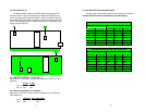
3.2 DIP Switch S1 & S4
The Models 593/25F, 593/45, and 593/TB features 2 four-position DIP
switches S1 and S4. Figure 3A (below) shows Models 593/TB & 593/45 top
view of the printed circuit board and where S1 and S4 are located. Figure 3B
shows Model 593/25 top view of the printed circuit board and the position of S1
and S4. Following figure 3A/3B is a detailed description on the different switch
settings and their functions.
3.3 Data Rates DIP Switch Setting S2 and S3
The table below shows the data rates DIP switch settings for S2 and S3.
Switches S2 and S3 must be set identically to operate properly.
S4
S1
Figure 3A. Models 593/TB & 593/45 Location of JP7 Pins 1-4 & JP8 Pins 1-4
Figure 3B. Model 593/25, Location of JP7 Pins 1-4 & JP8 Pins 1-4
Model 593 Series Data Rate Table
Switch Positions
Data Rates
S2 Position S3 Position 4800 bps 9600 kbps 19.2 kbps
S2-3 S3-3 OFF OFF OFF
S2-4 S3-4 OFF OFF OFF
S2-5 S3-5 OFF OFF OFF
S2-6 S3-6 OFF OFF ON
S2-7 S3-7 OFF ON OFF`
S2-8 S3-8 ON ON OFF
Model 593 Series Data Rate Table (continued)
Switch Positions
Data Rates
S2 Position S3 Position 38.4 kbps 57.6 kbps 115.2 kbps
S2-3 S3-3 OFF OFF ON
S2-4 S3-4 OFF ON ON
S2-5 S3-5 ON OFF OFF
S2-6 S3-6 OFF OFF OFF
S2-7 S3-7 OFF OFF OFF`
S2-8 S3-8 OFF OFF OFF
S1
S4
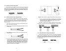
3.2.1 2W/4W Interface S1-1, 2 and S4-1, 2
Switches S1-1, 2 and S4-1, 2 set up the interface for 2 wire or 4 wire
operation.
3.2.2 Receive Impedance S1-3 and S4-3
Switches S1-3 and S4-3 set the receive impedance for 120 Ohms or
high impedance.
2 Wire 4 W
ire
S1-1, 2 ON OFF
S4-1, 2 ON OFF
120 Ohm High Impedance
S1-3 ON OFF
S4-3 ON OFF