


9 10
4.0 INSTALLATION
Once you have properly set the configuration switches and
jumpers, you are ready to connect Models 593/25F, 593/45, or 593/TB
to your system. This section tells you how to connect the interfaces
and how to operate your Model 593/25F, 593/45, or 593/TB.
4.1 CONNECTING TO THE RS-422 OR RS-485 INTERFACE
To function properly, the Models 593/25F, 593/45, and 593/TB
must have one or two pair of twisted pairs of metallic wire. These pairs
must be “dry” (unconditioned) metallic wire between 19 and 26 AWG.
The 593 Series has three physical interfaces as listed below.
Following the list is figure 4, which shows the location of the physical
interfaces.
1. Model 593/45: RJ-45 jacks on both sides
2. Model 593/TB: Terminal blocks with strain relief on both sides
3. Model 593/25F: DB-25 female connectors on both sides.
4.1.1 4-Wire Connection Using RJ-45
The RJ-45 connectors on the Model 593/45 are pre-wired for a
standard TELCO wiring enviroment. The signal/pin relationships are
shown below.
RJ-45
SIGNAL
1 ......................................N/C
2 ......................................GND*
3 ......................................RCV-
4 ......................................XMT+
5 ......................................XMT-
6 ......................................RCV+
7 ......................................GND*
8 ......................................N/C
*Connection to ground is optional
In most modular RS-422/RS-485 applications it is necessary to
use a "cross over" cable. The diagram below shows how a cross over
cable should be constructed for an environment where the Model
593/45 and the RS-422/RS-485 device uses a 8-wire RJ-45 connector.
Similar logic should be followed when using RJ-45 connectors or a
combintion of the two.
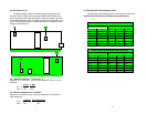
MODEL 593/45 RS-422/485 DEVICE
SIGNAL PIN# PIN# RS-422/485 SIGNAL
NC 1 -------------------N/C
GND 2 -------------------N/C
RCV- 3 -------------------5 XMT-
XMT+ 4 -------------------6 RCV+
XMT- 5 -------------------3 RCV-
RCV+ 6 -------------------4 XMT+
GND
†
7 -------------------N/C
N/C 8 -------------------N/C
1
2
3
4
5
6
7
8