


APPENDIX A
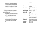
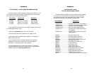
PATTON MODEL 1018 RC SPECIFICATIONS
Transmission Format: Asynchronous to terminals; synchronous
between units
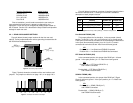
Internal Interface: Connection to Model 1000R16 rack
chassis via male card edge
External Interface: DB-25 female (RS-232), RJ-11 or RJ-45
(line)
Transmission Line: 4-wire unshielded twisted pair (UTP), 19-24
AWG
Asynchronous Data 1.2, 2.4, 4.8, 9.6, 19.2, 28.8,
Rates: 38.4 and 57.6 Kbps (switch selectable)
Link Clocking / Sync
Data Rate: Internal / 76.8 Kbps (fixed)
RTS/CTS Delay: No delay
Controls: Carrier constantly “ON” or “controlled by
DTR”
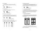
Indicators: Bi-color LED indicators for TD, RD, RTS &
DCD; single LED indicators for Test and
Error
Diagnostics: V.52 compliant bit error rate pattern; V.54
compliant— Local Analog Loopback and
Remote Digital Loopback, activated by front
panel switch or via terminal interface
Transformer Isolation: 1500 V RMS
Surge Protection: Silicon Avalanche Diodes
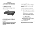
Power Supply: Rack-mount power supply is switchable
between 120V and 240V AC; chassis
supplies 10V AC to the Model 1018RC,
typical consumption is 700mW
Temperature: 0-50°C / 32-122°F
Humidity: 5-95%, non-condensing
Dimensions: 0.95”w x 3.1”h x 5.4”l
18
5. If the remote BER test indicates that errors
are
present, and
the local analog loopback/BER tests showed that both Model
1018RCs were functioning properly, this suggests a problem
with the twisted pair communication line connecting the two
modems. A common problem is improper crossing of the
pairs. Also, verify that the modular connections are pinned
properly, and the twisted pair line has continuity. If you still
have errors, call Technical Support at (301) 975-1007.
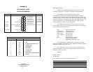
5.2.3 USING THE V.52 BER TEST INDEPENDENTLY
The Model 1018RC's V.52 BER test can be used independent of
the V.54 loopback tests. This requires two operators: one to initiate
and monitor the test at both the local and the remote Model 1018RC.
To use the V.52 BER test by itself, both operators should
simultaneously follow these steps:
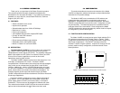
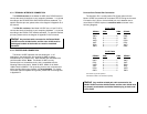
1. Locate the lower of the two toggle switches on the front panel
of the Model 1018RC and move it to the left. This will activate
the V.52 BER test mode and transmit a “511” test pattern to
the other unit. If any errors are present, the receiving
modem’s red “Error” LED will blink sporadically. Note: For
this independent test to function, the “511” switch on
both
Model 1018RCs must be turned on.
2. If the test indicates no errors are present, move the V.52
toggle switch to the right, thus activating the “511/E” test with
errors present. If the test is working properly, the receiving
modem’s red “Error” LED will glow. A successful “511/E” test
will confirm that the link is in place, and that the Model
1018RC’s built-in “511” generator and detector are working
properly.
17