


S1-3 through S1-6: Not Used
S1-7 and S1-8: RTS/CTS Delay
The combined settings for switches S1-7 and S1-8 determine the
amount of delay between the time the Model 1018RC “sees” RTS and
when it sends CTS. Currently, the Model 1018RC does not have
optional delay settings. “No Delay” is defined as between 500 nsec and
1 msec. The switches should remain in the “OFF” position.
S1-7
S1-8 Setting
Off Off 0 mS delay
No other valid settings
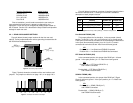
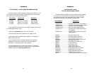
3.1.2 CONFIGURATION SWITCH SET “S2”
The eight DIP switches on pack S2 set Digital Reset, Carrier
Control, Link Clocking, Async Data Rate and Microprocessor Reset.
Factory default settings are summarized in Figure 4, below.
Descriptions of all possible S1 switch settings, including the Patton
factory default settings, are found on on pages 6 and 7.
6
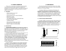
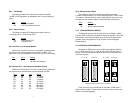
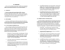
3.1.1 CONFIGURATION SWITCH PACK “S1”
The eight DIP switches on pack S1 set Remote Test Activation and
RTS/CTS Delay. Descriptions of all possible S1 switch settings,
including the Patton factory default settings, are found on on pages 4
and 5.
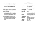
S1-1: DTE Control of LAL
The setting for switch S1-7 determines whether the Local Analog
Loopback test on the Model 1018RC can be activated via pin 18 of the
RS-232 interface.
S1-1 Setting
On Enabled
Off Disabled
S1-2: DTE Control of RDL
The setting for switch S1-7 determines whether the Remote Digital
Loopback test on the Model 1018RC can be activated via pin 21 of the
RS-232 interface.
S1-2 Setting
On Enabled
Off Disabled
5
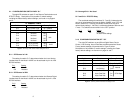
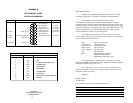
S2 SUMMARY TABLE
Position Function Factory Default
S2-1 V.54 Disable Off Normal
S2-2 Control of Carrier On Ctrl by DTR
S2-3 Link Clocking On
S2-4 Link Clocking On
S2-5 Async Data Rate On
S2-6 Async Data Rate On
S2-7 Async Data Rate On
S2-8 Microprocessor Reset Off Normal
57.6 Kbps
}
Figure 4. Summary of DIP switch default settings for S2
Internal
}
S1 SUMMARY TABLE
Position Function Factory Default
S1-1 DTE Control of LAL On Enabled
S1-2 DTE Control of RDL On Enabled
S1-3 Not Used Off
S1-4 Not Used Off
S1-5 Not Used Off
S1-6 Not Used Off
S1-7 RTS/CTS Delay Off
S1-8 RTS/CTS Delay Off
N/A
0 mS
}
}
Figure 3. Summary of DIP switch default settings for set S1