


9
4.0 INSTALLATION
Once the Model 2707 is properly configured, it is ready to connect to the
G.703 interface, to the serial port, and to the power source. This section
describes how to make these connections.
4.1 CONNECTING TO THE G.703 NETWORK
The Power, G.703 and serial Line connections are located on the rear
panel of the Model 2707. The following sections describe operation of
these connections.
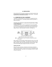
Connecting the 2707/D (X.21 version) Dual Coaxial Cable (75 Ohm)
to the G.703 Network
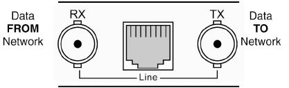
The Model 2707/D (X.21 version) is equipped with dual female BNCs
(TX and RX) for connection to a 75 Ohm dual coax G.703 network inter-
face. If your G.703 network terminates via dual coaxial cable, use the
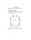
diagram below to make the proper connections. (SeeFigure 3).
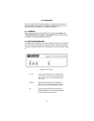
Figure 3.
Rear Panel, Showing Location of Connectors
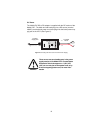
Note
The outer conductor of the coax cables are isolated from system
earth ground.
When using the 75 Ohm interface, jumper straps JP2, JP6, JP7, and JP5
must be installed over the jumpers. The jumpers are located next to the
BNC connectors. Refer to the following section to open the case. Open
the case and install jumper straps for JP2, JP6, JP7, and JP5.
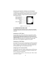
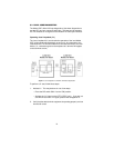
Opening the Case
Open the case by inserting a screwdriver into the slots and twist the
screwdriver head slightly. The top half of the case will separate from the
lower half of the case. Take caution not to damage any of the PC board
mounted components.