


10
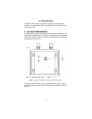
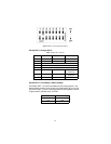
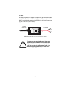
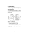
Connecting the Twisted Pair (120 Ohm) to the G.703 Network
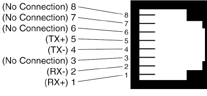
The Model 2707 is equipped with a single RJ-48C jack for connections to
a 120 Ohm twisted pair G.703 network interface. If your G.703 network
terminates via RJ-48C, use Figure 4 below to connect the 120 Ohm
G.703 network channel.
Figure 4.
G.703 120 Ohm Connection
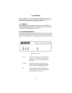
4.2 CONNECTING THE SERIAL PORT
The Model 2707/C and D supports V.35, X.21 serial port connections.
This section describes how to connect the serial ports to your terminal
equipment.
Connecting to a “DTE” Device
The serial port on the 2707/C (V.35 version) is hard-wired as a DCE.
Therefore these modules “want” to plug into a DTE such as a terminal,
PC or host. When making the connection to your DTE device, use a
straight through
cable of the shortest possible length—we recommend
6 feet or less. When purchasing or constructing an interface cable,
please refer to the pin diagrams in Appendix C as a guide.
Connecting to a “DCE” Device
If the Model 2707 serial interface is hard-wired as a DCE (all except the
X.21 version), you must use a null modem cable when connecting to a
modem, multiplexer or other DCE device. This cable should be of the
shortest possible length—we recommend 6 feet or less.
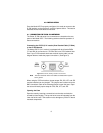
Configuring the X.21 Interface (2707/D)
The serial port on the X.21 interface is default wired as a DCE, but may
be switched to a DTE. This is done by reversing the orientation of the
DCE/DTE strap, as described below:
To reverse DCE/DTE orientation, remove the top case. Refer to “Open-
ing the Case” on page 9.