


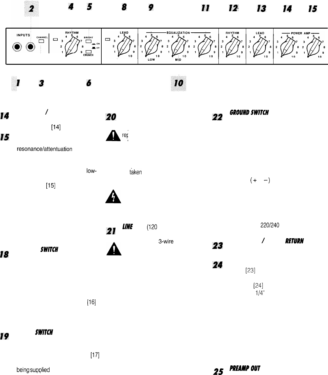
4
5
8
9
11
12,
13
14
I5
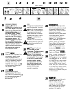
FRONT PANEL
HIGH NORMAL
I
lr
10
CRUNCH
GAIN
GAIN
PRE GAIN PRE GAIN
HIGH POST GAIN
POST GAIN
RESONANCE PRESENCE
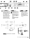
J4
15
18
19
1
3
6
RESONANCE
/
PRESENCE
Unique to the 5150, the
RESONANCE [14] control can be
set to boost the gain of the power
amp in the low frequencies at the
resonance/attentuation point of
the speaker cabinet. In simple
terms, the RESONANCE control
works like a low EQ to offset Iow-
end frequency drop-out. The
PRESENCE [15] control works in
the same manner, boosting the
high frequencies. Experimentation
using your particular speaker
cabinet along with personal taste
will determine your setting for
these important controls.
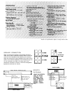
STANDBY SW/TCR
Allows the 5150 to be placed in a
non-operational standby mode.
When the standby switch is
activated the tubes remain hot and
ready for instantaneous operation,
eliminating warm-up time. The
STANDBY LED indicator light [16]
will illuminate when the amp is in
the operational mode.
POWER SW/TtN
Supplies power to the unit.
Depressed to the “ON” position,
the POWER LED indicator light
[17]
will illuminate indicating power is
beina
suDPlied
to the unit.
2l?
FUSE
A 5 amp fuse is located within the
A
cap of the fuseholder. It must be
A’
replaced with
the same type and
value in order to avoid damage to
the equipment and to prevent
voiding the warranty. If the amp
repeatedly blows fuses, it should
be
taken
to a qualified service
center for repair.
A
WARNING: The fuse should only
be replaced when the power cord
has been disconnected from its
21
power source.
f/NE
CORD
(120
V units only)
For your safety, we have
incorporated a 3-wire line (mains)
A
cable with proper grounding
facilities. It is not advisable to
remove the ground pin under any
circumstances. If it is necessary
to use the 5150 without proper
grounding facilities, suitable
grounding adaptors should be
used. Greatly reduced shock
hazard exists when the unit is
operated with the proper
grounded receptacles.
22
23
24
GROUND
SWITCH
Three position, rocker-type switch
which, for most applications, should
be operated in the center (zero)
position. If hum or noise is noticed
coming from the speaker
enclosure(s) with the ground switch
in the center position, place the
ground switch to positive or
negative
(+
or
-)
to minimize hum.
Should a hum/noise problem
continue, consult your authorized
Peavey Dealer, the Peavey factory,
or a qualified service technician.
NOTE: The ground switch is not
functional on
220/240
volt models.
EFFECTS SEND
/
EFFECTS
RETURN
Signals are supplied to outboard
effects or signal processing units
by patching from the EFFECTS
SEND
[23]
output into the outboard
unit(s) and back into the EFFECTS
RETURN
[24]
input using shielded
cable with
l/4”
phono jacks. Only
non gain effects devices (chorus,
reverb, delay, etc.) should be used
in the effects loop. Remote (on/off)
selection of outboard effects
devices can be achieved using the
5 150’s footswitch.
25
PREANPOUT
This output can be used to send a
preamped signal from the
5150 to a mixing console, tape
recorder, etc., using shielded
cable. Patching from the PREAMP
OUT does not affect the normal
operation of the amplifier.