


5 of 11
ISSUED: 1-11-08 SHEET #: 055-9495-2 10-16-08
Visit the Peerless Web Site at www.peerlessmounts.com
For customer care call 1-800-865-2112 or 708-865-8870.
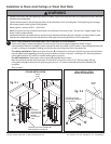
Installation to Wood Joist Ceilings or Wood Stud Walls
NOTE: Wall installation with models EXC, EXC-S and EXC-W is not available.
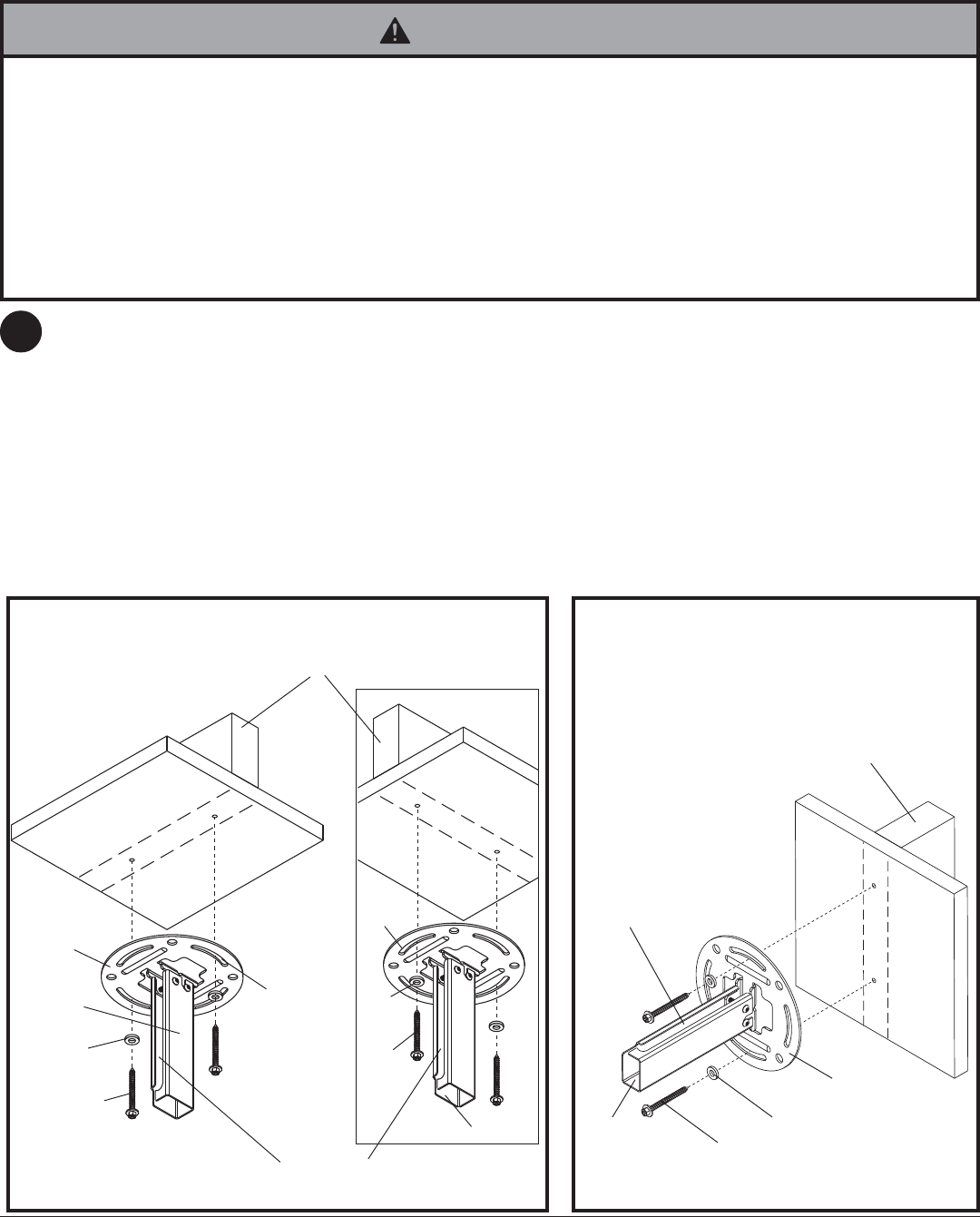
Use a stud finder to locate the edges of the stud or joist. Use of an edge-to-edge stud finder is highly
recommended. Based on its edges, draw a vertical line down the stud's or joist’s center. Place ceiling/wall plate (A)
on wall or ceiling as a template, making sure that the two mounting slots are on the centerline.
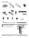
For ceiling installation: Opening on outer channel (B) indicates front of mount. Use the correct mounting slots on
the ceiling/wall plate depending on ceiling joist orientation as shown in figure 2.1 and figure 2.2. Mounting slots on
ceiling plate allow for 45° (±22.5) of rotation before securing to joist.
For wall installation: Opening on outer channel (B) indicates top of mount.
Mark the center of the two mounting holes. Drill two 5/32" (4 mm) dia. holes 2-1/2" (65 mm) deep. Secure
ceiling/wall plate (A) to wood stud or joist using two #14 x 2-1/2" wood screws (H) and two flat washers (O)
as shown.
Skip to step 3
• Installer must verify that the supporting surface will safely support the combined load of the equipment and all attached
hardware and components.
• Tighten wood screws so that ceiling/wall plate is firmly attached, but do not overtighten. Overtightening can damage
the screws, greatly reducing their holding power.
• Never tighten in excess of 80 in. • lb (9 N.M.).
• Make sure that mounting screws are anchored into the center of the stud or joist. The use of an "edge to edge" stud
finder is highly recommended.
• Hardware provided is for attachment of mount through standard thickness drywall or plaster into wood studs or joists.
Installers are responsible to provide hardware for other types of mounting situations (not UL approved).
WARNING
2
A
H
B
OPENING ON OUTER
CHANNEL (B) INDICATES
TOP OF MOUNT
fig. 2.3
WOOD
JOIST
fig. 2.2
H
A
OPENING ON OUTER CHANNEL (B)
INDICATES FRONT OF MOUNT
H
A
B
B
WOOD
STUD
fig. 2.1
CEILING INSTALLATION
WALL INSTALLATION
(EXCEPT FOR EXC MODELS)
MOUNTING
SLOTS ALLOW
FOR ROTATION
BEFORE
SECURING TO
JOIST
O
O
O