6 Pelco Manual C1902M (11/96)
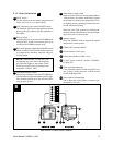
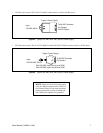
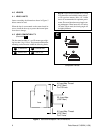
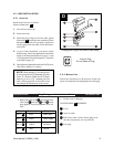
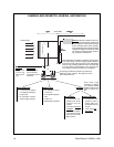
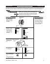
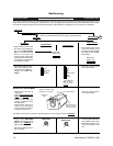
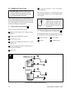
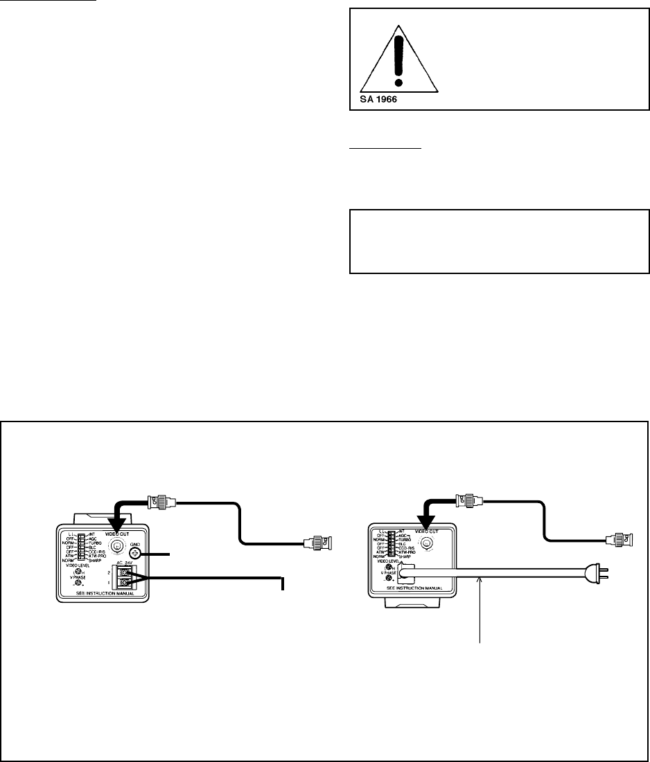
Figure 2. Rear Panels: CC4600-2/-2X and CC4600-3
3.0 POWER SUPPLY CONSIDERATIONS
Use only the recommended power supplies. Improper
substitutions may damage the camera or cause a shock
or fire hazard.
CC4600-2/2X
• The CC3300-2 must always be operated with a 24
VAC, Class 2 (60 Hz) power supply (not supplied).
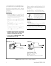
A wall transformer (as depicted in Figure 3) is an
example of a common power source.
• In the USA, use a power supply which is UL Listed.
In Canada, use a power supply which is CSA Cer-
tified.
• The CC4600-2X must always be operated with a
24 VAC (50 Hz) power supply.
• When connecting to the transformer, be sure to
carefully connect each lead to the appropriate ter-
minal. Wrong connections may cause malfunction
and/or damage to video camera.
• Ground the unit or an irregular voltage may be
generated in the AC power cord and may cause
malfunction or damage to the video camera.
• 24 VAC Cameras: do not exceed 24 VAC input.
Normal input voltage is 24 VAC
The power runs for user supplied wiring from a 24 VAC
supply to a CC3300-2 camera should be within the fol-
lowing limits:
Up to 60 m (200 ft) — 1 mm
2
(18 AWG) or larger.
Up to 100 m (325 ft) — 1.5 mm
2
(16 AWG) or larger
Do not mistakenly attach the
GND terminal on 24 VAC
cameras to either of the power
terminal inputs. Be sure to use
the grounding lug or screw.
CC4600-3
• The CC3300-3 must be always operated with a 220-
240 VAC, (50 Hz) power supply.
NOTE: The CC4600-3 is supplied with an
attached main power cable cord. See Figure 2
legend for power connections.
CC4600-3
POWER CONNECTIONS:
Brown Wire - Hot or Live wire
Blue Wire - Neutral wire
Green and Yellow wire - Earth Ground or GND
3
4
2
76
5
CC4600-2 & -2X
24VAC Input
GND


