


C2626M (2/07) 9
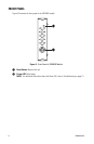
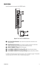
REAR PANEL
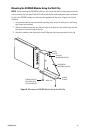
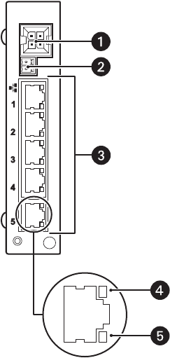
Figure 3 illustrates the rear panel of the SX8205R module.
Figure 3. Rear Panel of SX8205R Module
For additional information about rear-panel connections, refer to Installation on page 10. For detailed
information about the RJ-45 LEDs, refer to Troubleshooting on page 15.
ì Rack Power/Alarm Connector: 4-pin connector for power/alarm connection of rack-
mounted module
î Stand-Alone Power Connector: 2-pin connector for power connection of stand-alone
module; removable mating connector with screw terminals (not shown)
ï
10BASE-T/100BASE-TX Ports 1-5: RJ-45 connectors
ñ
RJ-45 10BASE-T/100BASE-TX Port Status LED, Left: Link/activity status indicator
ó
RJ-45 10BASE-T/100BASE-TX Port Status LED, Right: Duplex mode/collision indicator