6 Pelco Manual C653M-D (9/03)
You can use Table D as a guide to determine the necessary wire gauge (AWG) for various
cable distances that provide 24 VAC power. Or use it in a reverse fashion to determine the
maximum allowable cable distance for a particular wire gauge. Table D applies when using
2-conductor copper wire, with characteristics similar to West Penn 221-227 unshielded
cable. Calculations are based on a 10-percent voltage drop (generally the maximum
allowable drop for AC-powered devices).
The minimum acceptable voltage is calculated as follows:
24.0 VAC
-
02.4 (10%)
21.6 (Minimum Acceptable Voltage)
The minimum acceptable voltage used to create Table D was 21.6 volts. Therefore, the
24volt output has an acceptable range from 24 volts down to 21.6 volts; the 28 volt
output’s acceptable range is from 28 volts down to 21.6 volts.
Input Total VA Wire Gauge
Voltage Consumed 20 18 16
24 VAC 10 283 (86) 451 (137) 716 (218)
20 141 (42) 225 (68) 358 (109)
30 94 (28) 150 (45) 238 (72)
50 56 (17) 90 (27) 143 (43)
28 VAC 10 386 (117) 614 (187) 975 (297)
20 193 (58) 307 (93) 487 (148)
30 128 (39) 204 (62) 325 (99)
50 77 (23) 122 (37) 195 (59)
Table C. Recommended Wiring Distances
The following are the recommended maximum distances (transformer to load) and are
calculated with a 10-percent voltage drop. (Ten percent is generally the maximum allowable
voltage drop for AC-powered devices.)
Distances are calculated in feet; values in parenthe-
ses are meters.
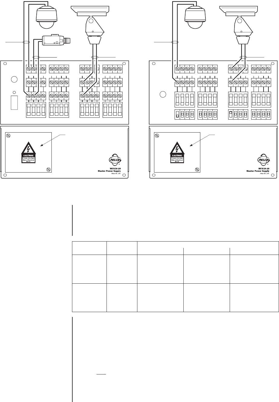
Figure 2. MCS Unit Wiring Connector Diagram
1234 5678 9101112 13141516
OUTPUT 1 THRU 8 OUTPUT 9 THRU 16
ON
OFF
Power
Main Fuse
OUTPUT # 1
(24 VAC)
OUTPUT # 2
(24 VAC)
OUTPUT # 9
(28 VAC)
24V
28V
COM
HIGH VOLTAGE
COMPARTMENT
PANEL
Figure 3. MCS “S” and “SB” Unit Wiring
Connector Diagram
1234 5678 9101112 13141516
Main Fuse
24V/28V
OUTPUT # 1
(28 VAC)
COM
24V
OFF
28V
OUTPUT # 9
(24 VAC)
HIGH VOLTAGE
COMPARTMENT
PANEL
