TROUBLESHOOTING
1. If none of the functions operate correctly, check the connection of the connectors to the receiver and pan/tilt.
2. If the connections are loose, tighten the lock ring on the connectors and then retest the pan/tilt functions.
3. If the connections are tight, check the Coaxitron receiver to determine if it is operating correctly. If the Coaxitron receiver is
operating correctly, there may be a problem with the cable. Contact Pelco for further technical troubleshooting aid.
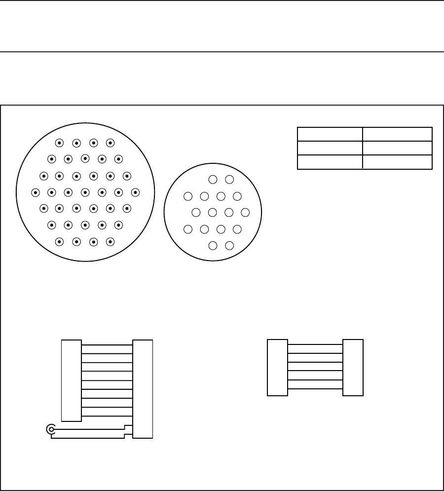
NOTE: If you find the unit has the pan and tilt functions operating backwards (for example, “Tilt Up” actually tilts down and “Pan Right”
actually pans left), pins 3 and 7 for pan and pins 5 and 6 for tilt have been reversed. The problem can be corrected in the field with a CPC
pin/socket extracting tool by exchanging the reversed function. If you do not have the necessary tool, contact Pelco for an RA number to
exchange the cable.
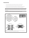
The following figure is a wiring diagram of the prewired cable. It may be used to troubleshoot wiring problems.
14
59
10 15
16 22
23 28
29 33
34 37
2
1
63
10 7
14
11
16
15
COMMON
LEFT
DOWN
UP
RIGHT
GROUND
CAMERA HI
CAMERA LOW
COMMON
LEFT
DOWN
UP
RIGHT
GROUND
CAMERA HI
CAMERA LOW
1
3
5
6
7
8
9
14
N/C
1
3
5
6
7
8
9
14
N/C
2
4
WHITE
BLACK
BROWN
BLUE
RED
GREEN
ORANGE
YELLOW
PURPLE
COAX CORE
COAX SHIELD
CONDUCTOR CABLE
RECEIVER SIDE PAN & TILT SIDE
6 CONDUCTOR CABLE
RECEIVER SIDE PAN & TILT SIDE
IRIS
FOCUS
ZOOM
LENS COMMON
ENC. AC
ENC. AC
IRIS
FOCUS
ZOOM
LENS COMMON
ENC. AC
ENC. AC
10
11
12
13
15
16
10
11
12
13
15
16
WHITE
RED
GREEN
BLACK
BROWN
BLUE
37 PINS
16 SOCKETS
CON206305-1 CON206037-1
CABLE PART # CABLE LENGTH
C6806 6 FT (1.83 M)
C6825 25 FT (7.62 M)
THIS DRAWING ALSO REPRESENTS C6825
CABLES.
CABLE LENGTHS SHOWN ABOVE.
NOTE: The receiver does not provide enclosure AC to the pan/tilt on pins 15 and 16. Pins 15 and 16 in the receiver are not
connected. You may choose to use those pins to provide enclosure AC to the pan/tilt.


