


C1632M-A (10/06) 7
Installation
The following items are supplied with each EPS5000-120.
1 Rack mount chassis
2 Snap-on ferrites
2 Power supplies (EPSPWR-120)
4 Power cords (2 USA standard and 2 European standard)
2 G-power cables (over-molded)
4 Screws, 10-32 x 0.750-inch, Phillips, pan head with washers
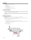
ATTACHING THE FERRITES
Two snap-on ferrites are supplied with the EPS5000-120 external power supply, one for each over-molded cable. Each ferrite must be attached to
the end of the over-molded cable that plugs into either an RK5000-3U or RK5000PS-3U. The ferrites must be attached to the over-molded cables
for the external power supply to comply with FCC and CE emissions requirements.
NOTE:
The ferrites should fit securely around the cables. If the ferrites are loose and slide along the cables, loop the cables through the ferrites
before closing the ferrites. If the thickness of the cables prevents the ferrites from closing, use a tie wrap to hold the ferrites in place rather than
looping the cables.
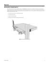
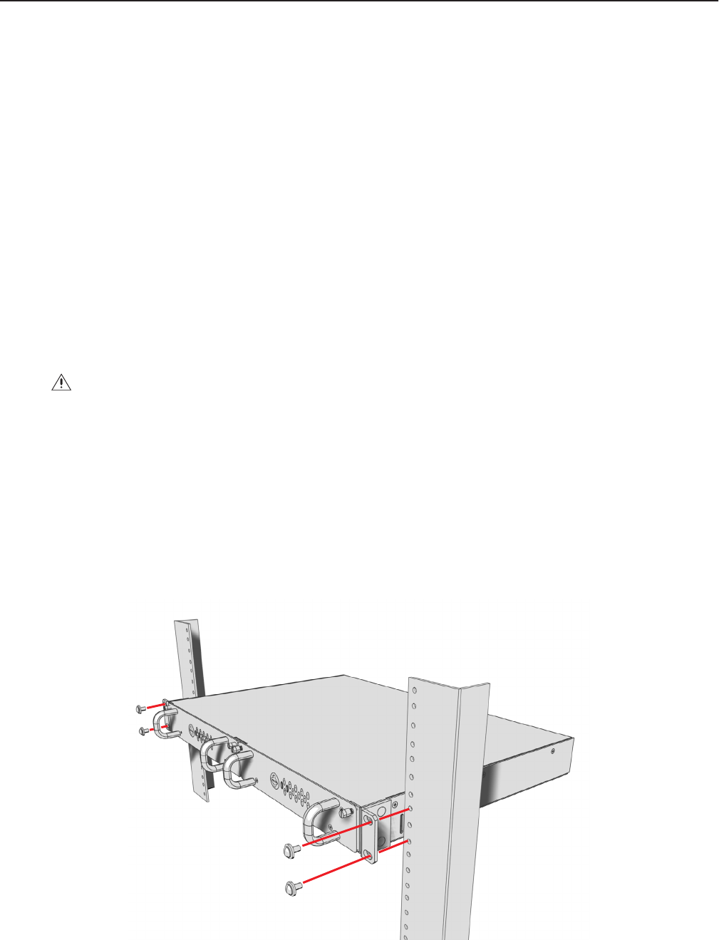
MOUNTING AN EPS5000-120
The external power supply, which is 1 RU high, can power up to two RK5000-3U chassis. It also provides redundant power when used with the
RK5000PS-3U. To mount an external power supply, follow these steps and refer to Figure 3.
1. Insert the EPS5000-120 into the rack.
2. Secure the EPS5000-120 to the rack with the four supplied 10-32 x 0.750-inch screws and washers.
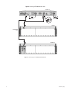
3. Connect each power supply to the rack using the supplied over-molded cables. Figure 4 shows the EPS5000-120 providing redundant power
to one RK5000PS-3U and powering one RK5000-3U.
4. Plug in the AC power cords.
5. Turn on the power supply switches.
WARNING:
To ensure adequate ventilation, 1 RU of space is required above and below the EPS5000-120.