


12 C1644M-B (6/06)
Installation
PACKAGE CONTENTS
The following items are supplied:
1 FT8304 transmitter or FR8304 receiver
1 Regulated switching power supply with four plug adapters (North American, Australian, U.K.,
and European configurations); 100-240 VAC, 50-60 Hz input, 12 VDC output
1Wall clip with two 4-40 x 0.250-inch Phillips pan head screws with lock washers
(for attachment of single module to wall)
1 FT8304/FR8304 Fiber Transmitter and Receiver Installation manual (this manual)
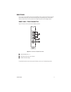
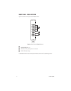
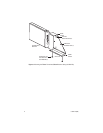
MOUNTING
The FT8304 transmitter/FR8304 receiver can be mounted into a rack or can be used as a stand-alone
module. As a stand-alone module, the unit can be placed on a desktop or can be mounted to a wall.
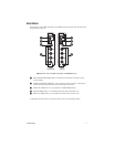
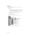
MOUNTING THE TRANSMITTER/RECEIVER INTO A RACK
The FT8304 transmitter/FR8304 receiver can be installed into an RK5000 Series rack mount chassis,
which can be mounted into an industry-standard 19-inch (48.26 cm) equipment rack. The RK5000
Series rack mount chassis includes the following models:
•
RK5000PS-3U
and
RK5000-3U:
Designed to accommodate fiber optic modules as follows:
–
The RK5000PS-3U rack mount chassis provides 12 single-width module slots and a
power supply.
–
The RK5000-3U rack mount chassis provides 14 single-width module slots (a power
supply is not included). Power to the modules can be supplied using the optional
external power supply (EPS5000-120).
For additional information, refer to the RK5000PS-3U/RK5000-3U Fiber Rack Mount Chassis
Installation manual.
•
RK5000PS-5U:
Designed to accommodate Endur
a
™
modules but can also accommodate fiber
optic modules with the use of the appropriate adapter kit. The RK5001-1UEXP adapter kit is
required for installation of the FT8304 transmitter/FR8304 receiver into the RK5000PS-5U
chassis.
For information about the RK5000PS-5U chassis, refer to the RK5000PS-5U Rack Mount Chassis
Installation manual.